Stringed
Musical Robot
Research project on
the development of new tools for musical expression
|
|
<Zibalo>

a hammered zither playing robot
dr.Godfried-Willem
RAES
2009-2025
|
In our quite large collection of musical instruments at Logos Foundation, we
had since very long a bunch of different Zithers of different kinds: German
made ones with some 48 steel strings, a Han-Koto as well as a few zithers stemming
from 19th century musical automatons. The latter I digged up from the cellar
of my grandmothers (Helena Strunz), 1899-1996) house. They were completely rusted...
For many years we had thoughts about finding a way to turn at least one of these
zithers into a musical robot. The problems, as soon as we started experimenting
and designing it on the drawing table seemed very insurmountable. The main reason
being the too close spacing of the strings. No matter what kind of plucking
mechanism we imagined, it either took too much physical space (using bi-directional
solenoids) or it would be way too slow and monophonic (using a sledge mechanism
with a single plectrum) to allow automation of all of them. So the idea was
dropped for many years.
In 2013 we were asked by Osama Abdulrassol to consider the automation of an
Arabic Qanun. The same problems we had analyzed already reappearing and some
new ones in top: the Qanun uses microtonal pitchchanges using a mechanically
pretty simple system (mandalar) , but again due to size/force constraints, very
difficult to automate well. Although in may 2013 we decided to have a throw
at it, and started making a first prototype for a plucking mechanism. The perspective
being to also make the zither itself rather than trying to automate an existing
instrument. For the first time in our career as a robot designer, we decided
to construct the automation mechanism prior to and fully independently of the
actual sounding instrument. This entails that we designed the actual instrument
only after the mechanism for the plucking was fully up and running. Thus, first
a prototype plucker was made using a solenoid assembly from Syndyne. Detailed
information about this design and its final failures can be found on the
legacy <Zi> webpage. The mechanism never had enough force to really
pluck the strings. Hence we recycled the mechanism and thus the
<Tinti> robot was eventually born...
A second attempt to build a plucking mechanism was made, making use of bi-directional
solenoids with permanent magnets. These solenoids are stable in either of their
end positions and they only require a pulse of changing polarity to make them
change position. As this type of solenoid could not be obtained with an anti-rotation
shaft, we decided to design round plectra with a 2 mm central hole for plucking
the strings. However, once more, it was a complete failure. The solenoids only
develop some force in either one of their end-positions, whereas for or a decent
plucking mechanism, most force is required in the middle of the trajectory.
Experiments we carried out prove that presumably the best pluckler mechanisms
can be made using stepping motors. As a consequence, spacing between the strings
has to be quite large, say at least some 50 mm.
Third time, good time as a Dutch proverb claims, we forsake the idea of plucking
and turned back to an old German made zither in mint condition. Instead of plucking,
now we used a hammering mechanism. So, organologically speaking, we turned the
project into some kind of cymbalon, a hammered citer after all. The hammering
mechanism was derived from the design of the 'poltergeist' we designed for our
<Ubu> robot. It uses small Binder solenoids to load a spring and on release
of the power, the anchor bounces back against the string. Velocity control is
very well possible by varying the pulse duration's. Very short pulses and quite
high voltages ( 48 V) are mandatory here. To understand the limits of velocities
versus repetition speed, it might be good to understand this graph:  The
solenoids, rated for 12V at 100% duty cycle work here with pulses of varying
duration (proportional to velocity) and a voltage of 48 V. So in order to avoid
overheating of the solenoids we have to make sure every pulse (tv) is followed
with a period of inactivity (ts) at least three times the duration of the pulse.
The
solenoids, rated for 12V at 100% duty cycle work here with pulses of varying
duration (proportional to velocity) and a voltage of 48 V. So in order to avoid
overheating of the solenoids we have to make sure every pulse (tv) is followed
with a period of inactivity (ts) at least three times the duration of the pulse.
Only when integrated in the context of our robot
orchestra with its wealth of varied sensor systems allowing full interactivity
with gesture as well as audio, this automate will become a true robot. That's
after all were its destination is to be sought.
Midi Mapping and implementation:
 This is the ambitus for
the instrument when using the original steel strings. This also is the ambitus
as implemented in MIDI.
This is the ambitus for
the instrument when using the original steel strings. This also is the ambitus
as implemented in MIDI.
Lights mapped on notes as:
- note 120: white frontal LED strip (automated whenever CC69 is 1)
- note 121: red LED lite (3 modules) between instrument and chassis plate
(automated whenever CC69 is 1)
- note 122: red LED spotlights to the ground. Velo steers PWM, although the
range is very limited..
- note 123: two 5W tubular tungsten lights left and right, front-sides of
the robot. ON/OFF only.
Midi channel: fixed to 4 (counting 0-15).
Note Off: Not at all required, unless automated repeats are used. In that case,
note off will stop the repetitions for that note..
Note On: Implemented for all notes in the range. Velo-byte is used for the
striking force. When repeats are active, note that all subsequent strokes will
be performed with the velocity as set with the first note-on command. The lights
are also mapped on notes, but make use of a range outside the normal range of
the zither.They are mapped on notes 120 to 123.
Channel aftertouch: can be used to let notes repeat automatically. The parameter
value sets the repeat frequency. Range: 4 Hz to 20 Hz. The command can be sent
even prior to note-on commands. The value sent will be preserved until reset
with either a new channel aftertouch command or an all notes off command.
Controller #66: Robot on/off switch. Sending a power off command (Ctrl 66 set
to 0) will cause a reset of all controllers to their default start up value.
Also settings for note repetition will be reset.
Controller #69: sets automation of the lights to on or off. By default this
is set to ON.
Controller #123: all notes off. Stops note repetitions and dims the lights.
Technical specifications:
- size: width: 450 mm, depth 540 mm, height 500 mm.
- weight: 12 kg. (estimated)
- transportation: needs a flightcase.
- power: 230 V ac / 200 W (peak, not playing: 5 W, normal playing < 20
W)
- Ambitus: 2 octaves. [midi 60 - 84] + 6 chords: C, G, A, D, E, F mapped on
midi notes 40 to 50
- Needs tuning before use!
- control: MIDI-input, 4 MIDI-Thru (differential)
- Insurance value: 4.500 Euro.
Design and construction: dr.Godfried-Willem
Raes
Collaborators on the construction of this robot:
- Hans Roels
- Bert Vandekerckhove (workshop assistant)
Music composed for <Zibalo>:
- Godfried-Willem Raes: 'Perpetuum Mobile' (6') [2025]
- Traditionals: 'Silent Night', 'O Tannenbaum'
<Zibalo> [
beknopte nederlandse voorstelling]
De zither waarvan we uitgingen bij de bouw van dit kleine robotje, hadden we
reeds in ons bezit van bij het ontstaan van de toenmalige werkgroep voor avant-garde
muziek, 'Logos'. We kregen het geschonken van een oude tante die het had gekocht
bij Cnudde, een in de jaren zestig erg bekende zaak voor piano's, partituren,
blokfluiten en andere kleine instrumenten, gelegen naast de aula van de Universiteit
in de Volderstraat. Het is een instrument van Oost-Duitse makelij, gebouwd in
de laten jaren '60 van vorige eeuw en voorzien van 25 'melodie' snaren en zes
vier-snarige akkoorden.
Al sedert het begin van het nieuwe millennium overwogen we en ondernamen
we ook meerdere praktische stappen- dit instrument te automatiseren, maar tot
nu toe waren al onze pogingen om een deugdelijk tokkelmechanisme zelf te ontwerpen
en te bouwen allesbehalve succesvol. In 2025 namen we de koe bij de horens en
besloten we de zaak helemaal anders aan te pakken. Hierbij dachten we eerder
aan een cimbalon of hakkebord, waarbij de snaren aangeklopt worden eerder dan
getokkeld. Voor het mechanisme daarvan kwamen kleine elektromagneetjes voorzien
van een sterk geveerd anker in aanmerking. Het zijn trekmagneetjes en daarvan
hadden we nog een grote voorraad. De klank ontstaat hier na de bekrachtiging
van het anker door de magneet: de magneet trekt het anker naar het vaste en
gesloten uiteinde van de spoel en spant zo de veer op, en pas wanneer de spoel
stroomloos wordt, springt het anker onder veerkracht uit de magneet en komt
zo in botsing met de snaar. Het mechanisme is erg geschikt voor het implementeren
van een genuanceerde aanslag. Dit was overigens ook al gebleken bij het ontwerp
van onze <Bello> robot,. waar dat principe ook werd toegepast.
De aan zo'n mechanisme inherente vertraging blijkt ik de praktijk helemaal geen
probleem te vormen omdat de duur van de bekrachtigingspulsen van de elektromagneten
nooit groter wordt dan ca. 3 ms, wat voor ons gehoor niet waarneembaar is. Voor
de automatisering van de akkoorden daarentegen, gebruikten we wat grotere cilindrische
elektromagneten die we voorzagen van met vilt beklede pianohamers. Elke hamer
slaat hier vier snaren tegelijk aan. Om dat te bereiken voorzagen we die pianohamers
van een afgeplat kontaktvlak. Dat kon eenvoudig gebeuren met een niet al te
fijne metaalvijl. Om het ronddraaien van de ankers tegen te gaan, pasten we
PTFE ('Teflon') geleiders toe.
Construction & Research Diary:
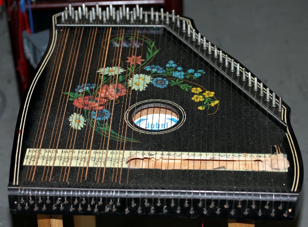
- 03.01.1969: We got a Zither as a birthday present from an aunt. It was purchased
at the 'Cnudde' music store, in those years housed in the Volderstraat, at
the left side of the University aula. The zither, branded 'Jubeltoene' was
made in the DDR in the late sixtees..For many of the following years it was
used as a sound source for the 'Logos werkgroep voor geengageerde avant-garde
muziek'.
- 03.03.2009: We were donated no less than 1500 telephone relays... Examining
weather or not these could be used in the automation we could make of our
Zither.
- 09.03.2009: Prototypes assembled using some 36 relays, with welded-on beaters.
Operation is sluggish and mechanically unreliable.
- 03.04.2010: Experiments with bi-directional solenoid driven pluckers. They
take up too much space, but do indeed work quite well.
- 19.12.2013: Experiments with Maxon DC motors, diameter 10mm and 13mm. This
works fine, although the mechanics for making this work reliably on an existing
Zither may become pretty complex and difficult in alignment.
- 13.05.2014: Bi-directional solenoid prototype prepared as plucking mechanism.
 This is a modification of an August Laukhuff part used for registration knobs
on pipe-organs (Catalogue nr. 3 002 00). The original manufacturer appeared
to be Syndyne, and after checking their
catalogue it became apparent that we could also get these parts without
an angled anchor. We ought to proceed a bit faster with this design as we
are urged to do so by 'De Centrale', who commissioned it for a collaborative
project with Abdullah Abdulrasol.
This is a modification of an August Laukhuff part used for registration knobs
on pipe-organs (Catalogue nr. 3 002 00). The original manufacturer appeared
to be Syndyne, and after checking their
catalogue it became apparent that we could also get these parts without
an angled anchor. We ought to proceed a bit faster with this design as we
are urged to do so by 'De Centrale', who commissioned it for a collaborative
project with Abdullah Abdulrasol.
- 14.05.2014: Syndyne contacted for custom made bi-directional solenoids.
As we plan to use pulse/hold boards for this instrument, we estimate that
the hold voltage should be no higher than 6 Volts, whereas the pulse voltage
may be very well be risen to 60 Volt. This ought to give a good range for
the velocity control. Plucking tests performed on a balalaika. In fact with
just 3 pluckers we could automate the balalaika but there is not enough space
on the neck to accommodate the required solenoids for the frets.
- 15.05.2014: Construction drawings for the complete plucker mechanism. Sketches
for the tuning mechanism: we consider using mandolin tuning pegs in rows of
four.
- 04.07.2014: All wiring done. Start of the first tests. As we didn't even
start making the actual stringed instrument, we perform the tests with the
above mentioned Zither, placed in an upright position. We use a lab power
supply adjusted to 6 V for the hold voltage and a -36 V power supply for the
negative pulse voltage. We observe excessive bouncing of the plectrum/anchor
combination. The pulse duration's have to be scaled down in the firmware.
- 06.08.2014: Tests with different plectrums and materials that can be used
as plectrums. Design of a new laboratory power supply with high current and
high voltage range. It should withstand highly inductive loads, this not being
the case for commercially available laboratory power supplies...
- 09.08.2014: Here is a link to our
app note for this new hefty power supply.
- 06-15.09.2014: Experiments and research with regard to the best plucker
shape, material and construction. The alignment promises to become an extremely
difficult and tedious task. So far, bone material as used on guitar bridges
seems to work best.
- 01.12.2014: Mounting of plectrums confined to Mattias Parent.
- 09.04.2015: Experiments performed with increased mass of the anchors in
order to increase plucking force. We can use small cube neodium magnets on
the one side, or try to obtain the equivalent through a different coding in
the firmware. We wired up a prototype board to perform these experiments.
The result were not worth the effort though.
- 23-24.04.2015: Further research and experiments by Mattias Parent.
- 06.08.2015: After many hours and days of experimenting we came to the conclusion
that the mechanism for the pluckers is unworkable. So we started a new design,
using linear bi-directional solenoids.
- 22.08.2015: Plectra made from nylon staff material on the lathe. Experiments
with plucking carried out on an old zither with steel strings. The plucking
does work indeed but we notice a click-noise on each position change of the
solenoid. Seems to be unavoidable.
- 23.08.2015: Further redesign of the Qanun. Considering to use the prototype
1 assembly for another robot, maybe <Tinti>,
using tiny bells...
- 30.09.2015: The missing and ordered bistable solenoids came in from Conrad,
so the works on the new plucker mechanism can continue.
- 02.10.2015: Helene Wolf contacted to help out with the design and cutting
of a new comb. As a cembalo maker, she ought to have the experience.
- 03.10.2015: Prototype board for the new solenoids etched, drilled and soldered.
We can test the first 8 solenoids if we have also the firmware ready. Work
for tomorrow...
- The PCB here is at 200% and should be reduced to 50% before printing and
exposing.
- 12-28.12.2015: Construction of a new bridge by Helene Wolf.
- 11.01.2016: Work on Zi taken up again.
- 26.01.2016: New bridges made by Helene Wolf presented and found to be excellent.
Start restringing the instrument.
- 19.02.2016: Sliding feet of the soundboard cut open again as the mechanism
was too stiff.
- 24.02.2016: Adjustment studs drilled and mounted to allow precise positioning
of the soundboard versus the plucking mechanism. For now using M6 threaded
rods, but this may become a larger size later on.
- 15.10.2016: All experiments with suitable plectrum material failed. The
problem that plagued our first and rejected design is reappearing: the solenoids
do not have enough power in the mid position. Furthermore, it appears unfeasible
to adjust the plucking distance reliably. As in top of all this bad luck,
we also lost all funding due to a corrupt, bad and big-ego oboist, Piet Van
Bockstal that issued a negative and canceling advise for funding against the
Logos Foundation. So, the project has to be placed on hold.
- 09.10.2024: <Zi> project taken up again. Considering to use linear
motors instead of solenoids. These for sure have enough power but they are
pretty slow... In principle we could use the same electronic circuits to drive
the motors. The firmware needs a complete revision and note repetitions seems
to be impossible, unless we allow only very slow repetitions...
- 10.10.2024: Two new PCB's etched and drilled.
- 11.10.2024: One board soldered. PCB layout improved.
- 12.10.2024: Second board soldered. Tests of the new firmware. Abandoning
all existing Zi hardware...
- ---------------------------------------------------------------------------------------------------------------------------------------------
- 12.11.2025: Work on the zither taken up again. The very successful poltergeist
mechanism we made for <Ubu>, gave us the idea to use some of the hundredths
of Binder 12V solenoids we have in stock as rebounce hammers. To be successful
we have to replace the springs with a much stronger type. The original springs
have following sizes:
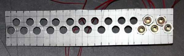
 The
thread for mounting the solenoids is M10x1 (metric extra fine). We made a
paper drawing (scale 1:1, or real size) of the string layout, useful for the
drilling works and precise placement of the solenoids:
The
thread for mounting the solenoids is M10x1 (metric extra fine). We made a
paper drawing (scale 1:1, or real size) of the string layout, useful for the
drilling works and precise placement of the solenoids: 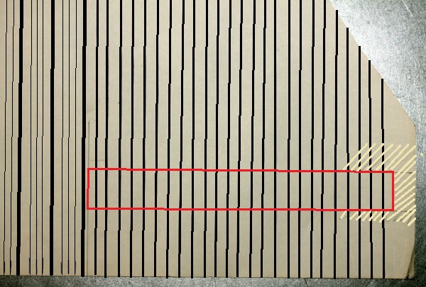
- 13.11.2025: It becomes mandatory to equip the Binder solenoids with much
stronger springs. Experiment performed: using a pressure spring (Fabory stock
item) 0.5 x 6.5 x 20, shortened to 7.5 mm (4 turns), works well with a supply
voltage of 48 V. Duty cycle should be kept smaller than 5%. Current is 240mA,
the coil resistance is 200 Ohms. Peak power follows as 11.5 Watt. For the
control we can use some older pulse-only PCB's. These were originally designed
for robots such as <Troms>, <Puff>, <Autosax> etc. As there
are 25 chromatic strings, we can even save some pins for the ICD. Each board
is designed for 16 pulse-only outputs. Here is the schematic:
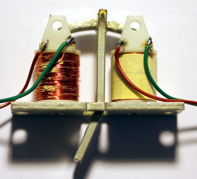
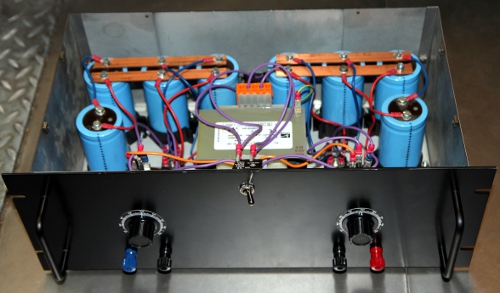
- 14.11.2025: Work on the 15-solenoid assembly. Not an easy undertaking under
narrow size constraints.
 This is the rudimentary construction, before trimming and adjusting to available
space.
This is the rudimentary construction, before trimming and adjusting to available
space. 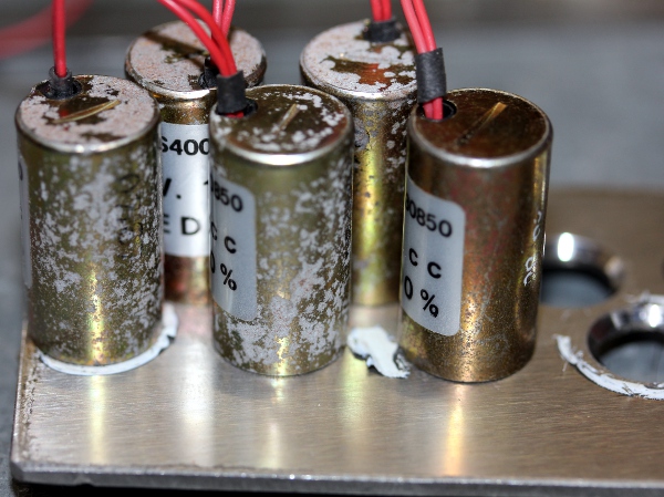 The solenoids,
although new, are dated 1967 and 1968. This explains the corrosion on the
bodies. Nevertheless, they work perfectly well.
The solenoids,
although new, are dated 1967 and 1968. This explains the corrosion on the
bodies. Nevertheless, they work perfectly well. 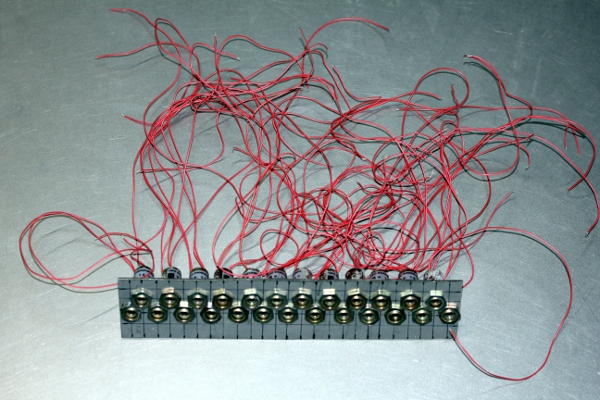 There are no traces of rust on the anchor's of the solenoids. A plastic cap
has protected the anchors as well as the spring against moisture.
There are no traces of rust on the anchor's of the solenoids. A plastic cap
has protected the anchors as well as the spring against moisture.
- 15.11.2025: Cut out through the Zither finished. Note that we did this without
even removing the strings. A risky undertaking...
 As for now, the solenoids assembly mounts from underneath the zither and is
fixed to the upperplate (the soundboard) with three M3 bolts. Later on we
may mount a few more bolts as the way it is now, feels a bit shaky.
As for now, the solenoids assembly mounts from underneath the zither and is
fixed to the upperplate (the soundboard) with three M3 bolts. Later on we
may mount a few more bolts as the way it is now, feels a bit shaky. 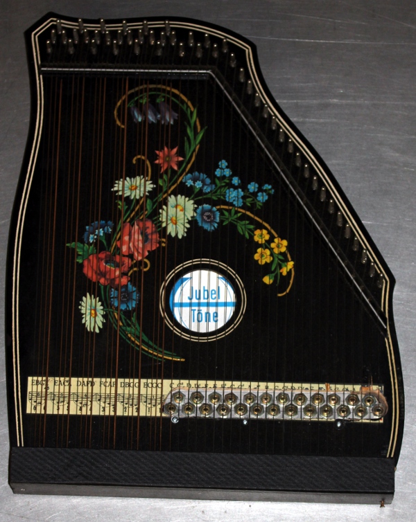 After mounting we noticed that all the strings went pretty much out of tune.
Probably we undermined some of the structural strength of the instrument by
removing too much wood at the right hand side. We had no choice though, as
we need some space to mount the solenoids for the top four strings. To give
the instrument some new and alternative structural strength, we made a curved
side plate in stainless steel, glued and mounted with screws on the right
side of the zither:
After mounting we noticed that all the strings went pretty much out of tune.
Probably we undermined some of the structural strength of the instrument by
removing too much wood at the right hand side. We had no choice though, as
we need some space to mount the solenoids for the top four strings. To give
the instrument some new and alternative structural strength, we made a curved
side plate in stainless steel, glued and mounted with screws on the right
side of the zither: 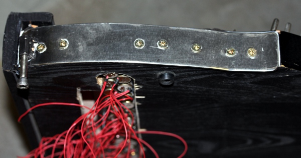
16.11.2025: Curved plates (35mm wide, 2mm thick) made and mounted for the
left side as well as for the top of the instrument. All three plates have
a welded on M6 high nut for mounting of the instrument on the chassis (to
be designed still). We foresaw two M6 high nuts on the left side reinforcing
plate, as this could come in handy in case we decide to automate the chords
as well. 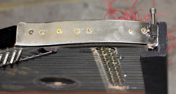 As today was
crafts-day, we opened up and welcomed quite some visitors to our workshop.
As today was
crafts-day, we opened up and welcomed quite some visitors to our workshop.
17.11.2025: Tests and designs for a hammering mechanism for the six chords.
We can use tubular solenoids, provided we equip them with an anti-rotation
shaft or another mechanism to avoid rotation of the anchors. We can use piano
hammers, provided we give them a more or less flat face on the felt hammertop.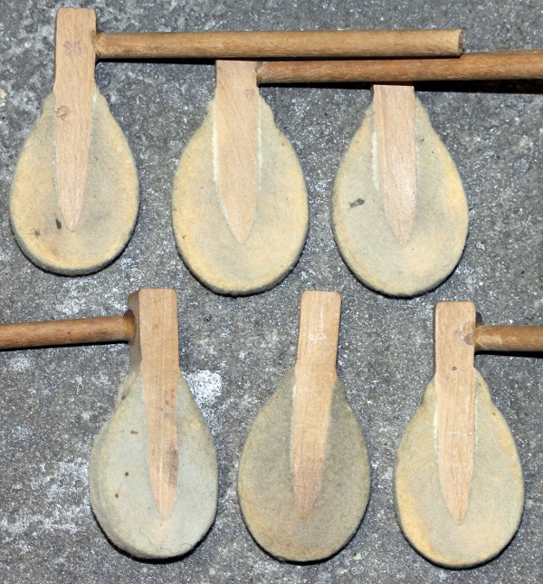
18.11.2025: Construction of the main chassis plate in stainless steel. Thickness
2 mm. Design of a suitable wheelbase.
19.11.2025: Frontal double wheel assembly prepared.
20.11.2025: Welding works. Chassis and wheelbase welded together. Mains power
entry mounted and wired. This IEC entry has a fuse holder. We should not forget
to insert a fuse in due time... As the pretty flat structure had a tendency
to bend, we TIG-welded a border, 10 mm high, on one of the sides. This ought
to make it very ridged now. 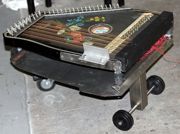
21.11.2025: Development of the firmware's for the hub and the pulse boards.
This is the mapping for the pulse boards: 
22.11.2025: Full implementation of <Zibalo> in GMT, including test and
torture code.
23.11.2025: Extensive testing of the hub board using GMT. This is the wiring
detail: 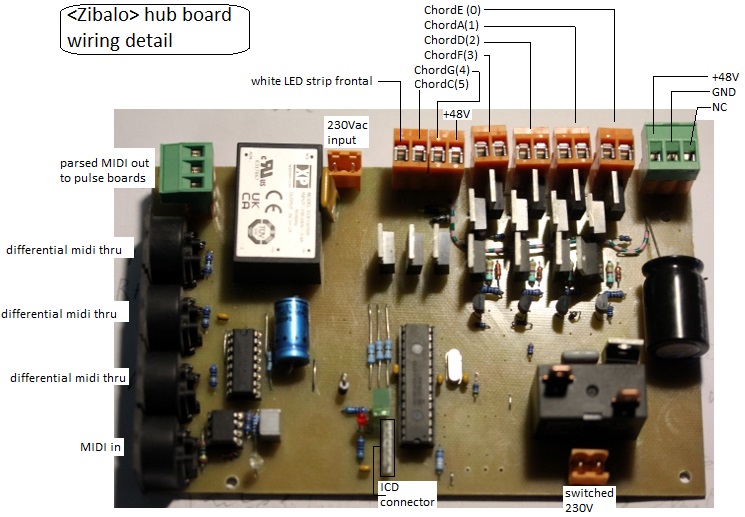 The pulse range
for the chord-hammers is now 3ms to 9.5ms. Loop speed for this microprocessor
is minimum 98kHz under maximum load conditions and maximum 128kHz at no load.
The pulse range
for the chord-hammers is now 3ms to 9.5ms. Loop speed for this microprocessor
is minimum 98kHz under maximum load conditions and maximum 128kHz at no load.
24.11.2025: Recycled 16-pulse output board patched for use in <Zibalo>.
This board, servicing note 60 to 72, was firstly used for <Autosax>
in 2005. We mounted an ICD programming connector, glued to the PCB with epoxy
rosin. The wiring and connections now look like this: 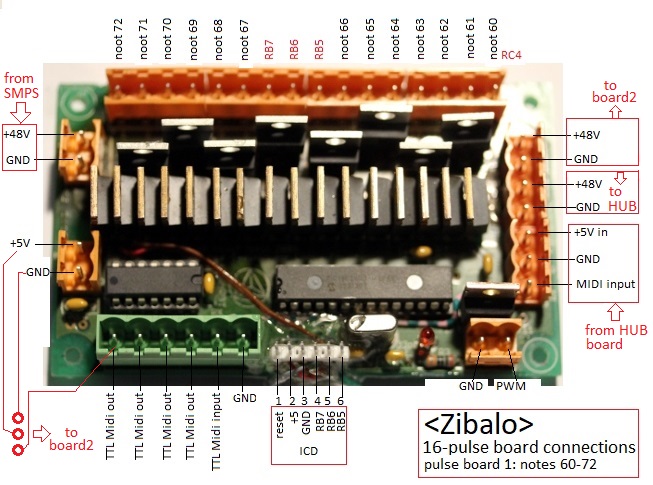 We used MUR620C double diodes here. The mosfets are IRL640. The microprocessor
is an old 18F2525. First version of the firmware uploaded in the microprocessor.
On board2, the mosfets used are PHP79NQ08LT types (Nexperia) . This type is
now obsolete but we had enough stock for this project. The short specs are
73 A - 75 V , Ug = 5 V, Ron = 0.014 Ohm. On board 2, the diodes are the same
as on board1 : MUR620C.
We used MUR620C double diodes here. The mosfets are IRL640. The microprocessor
is an old 18F2525. First version of the firmware uploaded in the microprocessor.
On board2, the mosfets used are PHP79NQ08LT types (Nexperia) . This type is
now obsolete but we had enough stock for this project. The short specs are
73 A - 75 V , Ug = 5 V, Ron = 0.014 Ohm. On board 2, the diodes are the same
as on board1 : MUR620C.
25.11.2025: Finishing soldering work for pulse board 2. 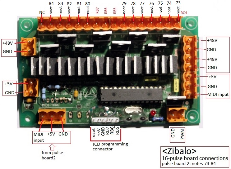 The microprocessor is an 18F2525, the last one of that type we had in stock.
26.11.2025: Start mounting of the PCB's on the chassis. Placement of the lights
mapped on 120, 121, 122. No idea yet for lite 123... Could be tungsten ( 2
x 24V with E14 sockets) Mounting of the 12V - 2A SMPS (encapsulated Vigortronix
unit) on the chassis.
27.11.2025: Wiring of all components on the chassis. We decided to mount two
tungsten bulbs with Festoon sockets: 2 x 24 V in series, connected to pulseboard
on the last output after note 84. This tungsten light is mapped on midi note
123, on-off only. 
28.11.2025: M6 shock absorbers ordered from MEA. Finalizing work on the distance
holders between zither and mounting plate, such that we can reach the connectors
with our hands. Should we make a new frontplate?
29.11.2025: all wiring finished. Boot test passed, as yet without midi. Anchors
equipped with newly cut springs and placed back into the solenoids. If we
are careful this can be done without removing the solenoid assembly.
30.11.2025: Complete tuning session. Midi connected and testing with the test-code
in GMT. Scale test passed, although we have some force irregularities due
to unequal springs. At first sight, it seems we can even reduce the scaling
of the velo-pulses. Very fast note repetitions give no problems at all. 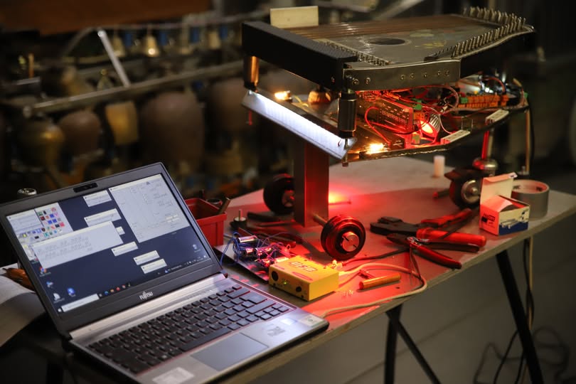 Firmware changed: channel aftertouch fully implemented now for note repetitions.
Minimum repetition speed will be ca. 4Hz, maximum ca. 20Hz.
Firmware changed: channel aftertouch fully implemented now for note repetitions.
Minimum repetition speed will be ca. 4Hz, maximum ca. 20Hz.
01.12.2025: Operating conditions as implemented in the firmware documented
in a graph: We finished
implementing fast repetitions, using the channel aftertouch command. Repetition
rates faster than 20Hz seem to be very well possible.
02.12.2025: Further work on the firmware. A mysterious bug puzzles us and
we lost the full day on debugging... in vain.
03.12.2025: Two bugs found: the first one is actually a compiler bug: if the
code between IF ... THEN... ELSE get's over an undocumented limit, the entire
code stops working... The second bug was our own mistake: we wrote in a single
instance idx = SortTimers, where it had to be idx = SortTimers (). When we
omit the empty brackets, the function always returns &HFF in idx. All
chips programmed with the new firmware. Further work on the hammers for the
chords. The solenoid anchors have to get an M2.5 thread such that we can fine-adjust
their vertical position. The wood on the hammers get an internal M2.5 thread
as well. PTFE-spacers made to work as anti rotation shafts for the hammers.
Once more we have a job for a metal milling machine but unfortunately, we
sadly cannot afford one... It would make the perfect tool for constructing
an adjustable hammer assembly. 
04.12.2025: Further work on the hammer assembly. Standoff plates welded on
to make sure the assembly can be mounted parallel to the soundboard. L-shaped
solenoid holder welded on. Solenoids bolted on. Hammers roughly cut to size.
Wiring of the solenoids. We use color codes for the wires: black. brown, pink,
orange. yellow, green for C, G, F, D, A, E chords or resp. 48, 43, 41, 50,
45, 40. The red wire is 48V. Very first test with 1 solenoid passed.
05.12.2025: Finalising the hammer assembly. We labelled the hamers, as we
had to file the felt different for every chord. Note that all four strings
in each chord have a different thickness. Complete tuning session. Measuring
the velocity ranges for all the solenoids such that we can optimize the firmware.
First real 'portrait' pictures made of the newborn robot:
06.12.2025: Bizarre failure... We checked the velocity ranges for the Binder
solenoids and noticed that we need abour 4 times larger pulse durations as
compared to yesterday... Also, the hammers refuse to pulse properly... Checking
the 48V XP-power SMPS, we measured a quite shaky 22 V. Even if we remove all
load, the output voltage stayed that low. The 'power-good' LED lights up!
Clearly the (new!) power supply - XP-Power type VCS100US48- failed. This obviously
explains the range change for the Binder solenoids. However, it does not explain
the refusal of the hammers steered by the hub board. On the testboard, the
firmware seems to do exactly what it is supposed to do: giving pulses in the
range3.2ms to 9.5 ms. We ordered new power supplies from Farnell, avoiding
XP-Power devices this time, we choose
Meanwell Medical RPS-200-48C. Maybe we should build in a small analog
voltmeter to monitor the power supply...
07.12.2025: As in absense of a 48V power supply we cannot proceed in finalizing
the project, we decided to build a 'classical' analog power supply from components
we had on the shelves in the lab. Once more it confronts us with an observation that puzzles us since our childhood,
when we started our carreer in electronics: according to the textbooks, the
rectified voltage measured over the capacitor is 52.9V whereas we would expect
(35V - 0.4V) * SQR(2) = 48.93 V, or if we ommit the voltage drop over the
diode, 49.49 V. How should we explain the ca. 5% difference? Anyhow, we wired
the new analog supply and everything works again as before. A mechanical problem
has risen up now: the transformer with its weight of ca. 2.5 kg tends to bring
the three-wheel construction out of equilitrium. We can only bring it back
in balance by adding a 2 kg weight on the extreme right side...
Once more it confronts us with an observation that puzzles us since our childhood,
when we started our carreer in electronics: according to the textbooks, the
rectified voltage measured over the capacitor is 52.9V whereas we would expect
(35V - 0.4V) * SQR(2) = 48.93 V, or if we ommit the voltage drop over the
diode, 49.49 V. How should we explain the ca. 5% difference? Anyhow, we wired
the new analog supply and everything works again as before. A mechanical problem
has risen up now: the transformer with its weight of ca. 2.5 kg tends to bring
the three-wheel construction out of equilitrium. We can only bring it back
in balance by adding a 2 kg weight on the extreme right side...
08.12.2025: Balancing weight in red copper made: 50 mm massive staf, cut to
12 cm gives 2 kg. For pure copper we have 8.9 kg / liter. Hub firmware improved
and uploaded. Examining the problem with note 82 on the second pulse-board.
Carefull analysis revealed some of the pins if the 18F2525 chips are not functioning.
The chip is to be disposed off. We replaced it with a new 18F2620 chip and
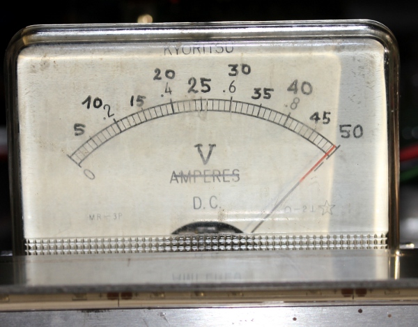
everything seems to work as it should now. We decided to mount a panelmeter
on the front, such that we van monitor the 48 V power. We used an old Kyuritsu
A-meter, removed the internal shunt and calculated a new series resistor to
make a full scale 50 V DC meter.  As the metering components provide a leak and discharge path for the 10mF
capacitance, the voltage will slowly decay to zero after a power shut down.
As the metering components provide a leak and discharge path for the 10mF
capacitance, the voltage will slowly decay to zero after a power shut down.
 Further testing has led
to the decision to change the velocity scaling for the pulse boards. The low
side is o.k. now, but the range 70 to 127 is useless.
Further testing has led
to the decision to change the velocity scaling for the pulse boards. The low
side is o.k. now, but the range 70 to 127 is useless.
09.12.2025: The bug with the hammers is persistent but difficult to provoke.
The velo-pulse mechanism fails every so often. Timer refresh instruction added
in the check-timers routine. This seems to work at first sight. Apparently
the midi-parser causes time errors when a lot of midi messages are to be sent
out. Two christmess files prepared for the concert on thursday 18th of december:
'Silent Night' and 'O Tannenbaum'.
10.12.2025: Glueing a piece of thick felt to dampen the sound of the hammers
on their return after striking. Demo piece for <Zibalo> composed: 'Perpetuum
Mobile', duration is six minutes.
11.12.2025: All lookup tables for the velocities changed to quadratic instead
of linear: this gives a much improved scaling. Frontal light on the scale
of the voltmeter added. This LED assembly has a 2500 Ohms wirewound series
resistor, such that the current is limited to ca. 13 mA. This light follows
the presence of the 48 V power and as such reflects controller 66. <Zibalo>
demonstrated for Mattias Parent. We found a quite elegant solution for the
required balancing weight: instead of mounting a massive copper cylinder,
we can place a heavy permanent magnet (taken from an old loudspeaker) that
can be usefull for storing the ferromagnetic tuning key inside the robot.
12-15.2025: work on orchestrations with a part for zibalo in preparation for
our end-of-the-year concert.
18.12.2025: <Zibalo> passed the tests on the public concert tonite,
where it performed succesfully in four different compositions.
-
TO DO:.
- cutting and placing the best possible springs in the Binder solenoids.
- retuning
- Final scaling of the velocities and repeat frequencies to realistic
values.
Last update: 2025-12-19
by Godfried-Willem Raes
The following information is not intended for the general public nor is
it required for composers wanting to make use of our <Zibalo> robot,
but is essential for maintenance and servicing of the robot by our collaborators.
It also might be usefull for people that want to undertake similar projects.
Feedback is mostly welcomed.
Technical drawings, specs
and data sheets:
Power supplies:
- +5 V DC - 2A (Logic and microcontrollers), XP-Power ECE10US05
- +48V DC - 4.5A (solenoids), analog power supply. [also in stock as a
spare part: Meanwell Medical
RPS-200-48C. ]
- +12V DC - 2A (lights) Vigortronix unit.
Wiring & circuit details midihub board, servicing the six chord hammers
and the white frontal light.:
-
Circuit details solenoid driver boards:
- The three LED-strips
connected on the GND-PWM connector are OMC LTD01209 LMMR1, 12V, RED.
- Pulse board 2: The
red spotlights connected on the GND-PWM connector are Paulmann GU5.3 2.5W
and 3W. On the output marked NC we connected two 24 V -5 W bulbs with festoon
sockets, connected in series. The sockets are BS242 (JKL Components, part#
2131124.
- Analog 48 V power supply:
- LED-scale light: LFBML-24V-6S167, 1 flexible 6-led unit. www.ledxon.com,
60mA / unit. With the 2k5 resistor in series, current drawn is limited to
less than 15 mA.
-
Criticism:
- Hammering the zither strings indeed does work, but the sound volume is pretty
low.
-
References:
Meanwell Medical RPS-200-48C.
(datasheet)
- Microchip PIC
18F2525 manual
RAES, Godfried-Willem, "Expression
control in musical automates", 1977/2025
ROSSING, Thomas.D (editor), "The Science of String Instruments"
, ed: Springer NY, Stanford CCRMA, 2010 ISBN 978-1-4419-7109-8
SMIT, Thorsten a.o.,
'A highly accurate plucking mechanism for acoustical measurements of stringed
instruments', in: Journal of the Acoustical Society of America, EL223,
may 2010.
Syndyne catalogue
Wikipedia entry on the Qanun.