Musical
Robot
Research project on
the development of new tools for musical expression at the Ghent
University

|
|
<Zi>

an attempt to make an automated Qanun
dr.Godfried-Willem
RAES
2009-2016-2024
|
In our quite large collection of musical instruments at Logos
Foundation, we had since long a bunch of different Zithers of different
kinds: German made ones with some 48 steel strings, a Han-Koto as well
as a few zithers stemming from 19th century musical automatons. For
many years we had thoughts about finding a way to turn at least one of
these into a musical robot. The problems, as soon as we started
designing it on the drawing table seemed very unsurmountable. The main
reason being the too close spacing of the strings. No matter what kind
of plucking mechanism we imagined, it either took too much physical
space (using bidirectional solenoids) or it would be way too slow and
monophonic (using a sledge mechanism with a single plectrum) to allow
automation of all of them. So the idea was dropped for many years.
In 2013 we were asked by Osama Abdulrassol to consider the
automation of an arabic Qanun. The same problems we had analysed
already reappearing and some new ones in top: the Qanun uses microtonal
pitchchanges using a mechanically pretty simple system (mandalar) , but
again due to size/force constraints, very difficult to automate well.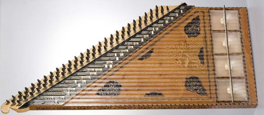
In may 2013 we decided to have a throw at it, and started making a first prototype
for a plucking mechanism. The perspective being to also make the zither itself
rather than trying to automate an existing instrument. For the first time in
our carreer as a robot designer, we decided to construct the automation mechanism
prior to and fully independently of the actual sounding instrument. This entails
that we designed the actual instrument only after the mechanism for the plucking
was fully up and running. Thus, first a prototype plucker was made using a solenoid
assembly from Syndyne: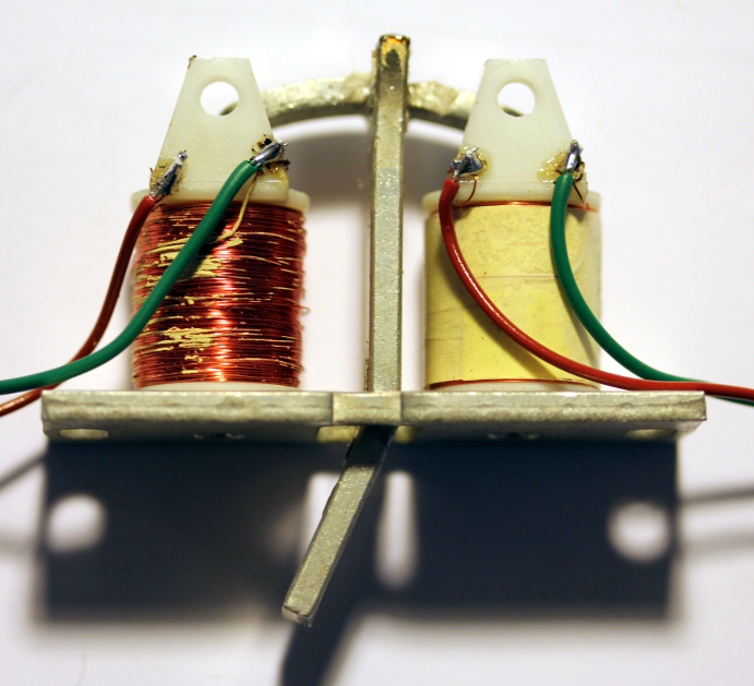 These
components are normally used as register knobs on pipe organs with electromagnetic
registration. We contacted the factory in order to obtain these components with
a straight anchor, as this would be much easier to attach the plectra. If we
use four rows of pluckers, and using a somewhat weird order of strings it appeared
possible to design the zither with a string distance of 15 mm. So for a 3 octave
instrument, the width could be limited to ca. 60 cm. We made a plucker assembly
for a maximum of 38 strings, welded from stainless steel. The electronics require
twice as many pulse/hold circuits and thus we needed no less than six driver
boards and microprocessors. These boards are the same as the ones we developed
for <Qt>, <Bomi> and a few more robots where velocity control combined
with a hold function was needed. The boards have a maximum of 14 outputs each
and taking into acount that here we need two outputs for each string, we need
one board for every seven strings. The strange order of the strings was caused
by the design rule dictating the strings to be plucked at about 1/7th of their
lenght.
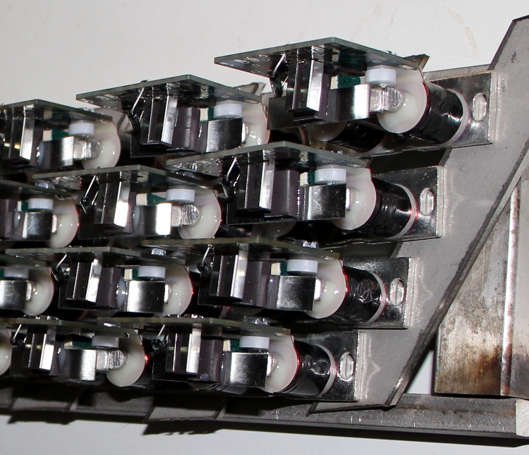
  The picture
shows the plucker mechanism with associated electronics before wiring.
The circuit for the control of this prototype bidirectional solenoid assembly
for each of the strings is given below:

As the pluckers at all times had to be in a deterministic position, it was
impossible to implement a true power off for this robot. Only on cold boot,
the pluckers will all go to a left position and thus pluck quite a few strings
and sounding a cluster of notes. If we would implement a true power-off, this
unwanted noise would be produced on any power on command. This implies that
at any time when the robot is switched on, now allways 38 solenoids will be
active in their position-hold state.
It took us more than two months to finish this prototype plucking mechanism.
As soon as this was ready we started experimenting and designing the actual
instrument in function of the possibilities of the mechanism. Parameters that
were fixed are the distance between strings (ca. 15mm), the shortest possible
string and therewith the highest possible note and last but not least, the maximum
thickness and force on the strings as this is limited by the maximum force the
pluckers can deliver. This drove our designs into the direction of using carbon
fiber or nylon strings as used on the qanun and using expanded polystyrene as
soundboard material. The <Rodo> robot, designed
earlier was our first attempt to use this material for a soundboard and was
proven to be pretty succesfull. Moreover, as the traditional qanun uses a bridge
resting at 4 to 5 points on stretched membranes (in this respect it shows some
acoustic similarity with the banjo), the idea to go for a styrofoam soundboard
is not at all alien to the instrument.
We forsake the use of double or triple strings for each note as we
could not make this to work properly with our pivoting plucking
mechanism. So we went for 38 single strings, however, tuned
chromatically. (Qanuns have a diatonic tuning). For the tuning mechanism, after long experiments using
mandolin tuning pegs in rows of four which came out to be unworkable,
we designed a simple yet very effective mechanism. The advantage of our
mechanism is that the strings are tensioned by pulling only and thus we
can avoid any torsional forces in the strings as would have been the
case if we rolled them on a cylinder as usually done. Another advantage
of our mechanism is that close spacing of the pegs is easy to achieve.
So, all tuning pegs could be arranged in a single row. Here is a
picture of the prototype of the mechanism:

Users have to be carefull in tensioning the small M4 nut, if the tension is
too high the string will be cut off! Tension should be just such as to prevent
the string from sliding out. As an alternative to using the M4 nut, one can
also make a knot around the tuning peg. This mechanism makes it perfectly possible
to implement mandalar, by inserting small fork inserts between the long hexagonal
tuning nut and the holder plate. However, we did not consider automation of
such devices in this robot, mainly because it would make the whole construction
way to heavy.
<Zi> being a string instrument, it will be clear that it cannot be used
without proper maintenance. Not only users will have to tune the instrument
properly, but also the bridges and the plectrums may need regular attention.
This is because in tuning, the bridges may move slightly and may cause the plectrums
to get out of adjustment. Bowed string instrument players will certainly be
familiar with this problem. The need for regular tuning arises from the use
of nylon strings. Had we used steel, the tuning would be a lot more stable,
but the tone quality would be far off the gentle qanun sound we had in mind
in the design.
The original string order and lay out looked like: The string gages used as well as the sounding string lenghts are given in the
table.
After many months of experimenting and trying to get the plectrums adjusted
properly, we had to confess that the design of the plucker mechanism was a complete
failure. We gave it up altogether and decided to design a second prototype.
This time using longitudinal bidirectional solenoids with permanent magnets.
These solenoids are stable in either of their end positions and they only require
a pulse of changing polarity to make them change position. As this type of solenoid
could not be obtained with an anti-rotation shaft, we decided to design round
plectra with a 2 mm central hole for plucking the strings. The plectra are mounted
on the shafts with two stainless steel M2 nuts.
Not only the plucker assembly had to be completely build again and redesigned,
but also the electronics, including the power supply. This type of solenoid
requires pulses of alternating polarity, thus requiring H-bridges to drive them.
We used an old and proven H-bridge in IC form, the L298N. With a single 18F2525
microprocessor chip, we can steer a group of 8 solenoids. Here is the circuit:
 Five
of these boards are required for the complete qanun. The power requirements
are a lot more relaxed as compared to the first prototype design. This mainly
because of the pulse-only operation of the solenoids. However, these solenoids
having a DC resistance of only 4.2 Ohms, draw a pulse current of 2.8A each,
which is at the limit of what the L298 drivers can cope with. The data sheet
specifies a maximum of 3A, non repetitive pulse. The pulses being limited to
maximum 50ms with a 50% duty cycle relaxes the limits though. Unfortunately
there is as yet no integrated mosfet H-bridge on the market with a wider range.
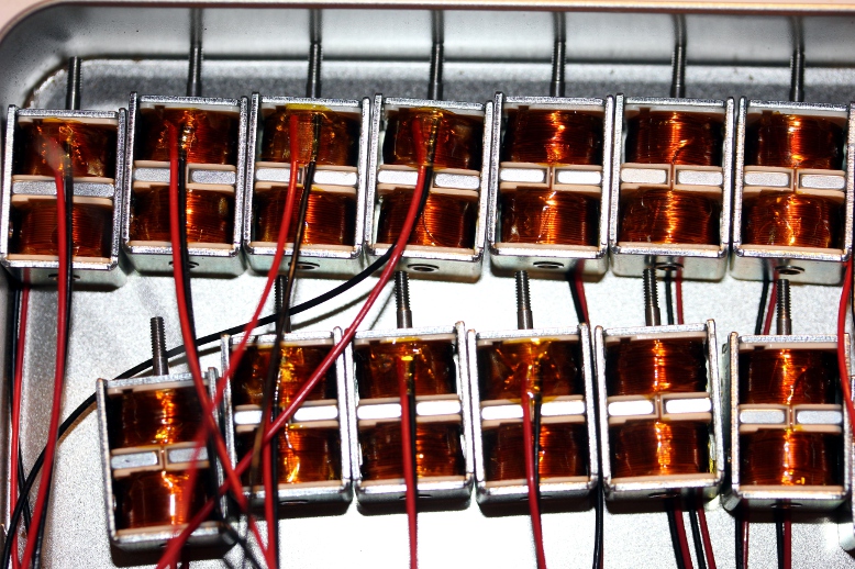
As to the power supply, a 12V / 500VA transformer and some parallelled LT1024-12V
regulators seemed adequate. Here is a picture of these solenoids:
Midi Mapping and implementation:
 This is the ambitus for the instrument when using a complete set of Qanun strings.
This also is the ambitus as implemented in MIDI.
However, this ambitus was at the original base of our design: 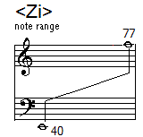 To reach this ambitus, guitar strings can be used. Obviously, if other strings
are used, other tunings are certainly possible. The instrument would than behave
as a transposing instrument and should be treated accordingly. The lowest note
in the original design (40), low E corresponds to the lowest note on the guitar
and will apply if the instrument is strung with guitar strings. As to
the Qanun, there is no real standard for the ambitus of the traditional Qanun,
although midi 50 (D) to 93 (a''), diatonic, is commonly found in Turkey.
Midi channel: fixed to 4 (counting 0-15).
Note Off: Implemented for all notes in the range. Note Off does not reset the
repetition rate.
Note On: Implemented for notes in the range. Velo-byte is used for the striking
force. The range is rather limited. The lights are also mapped on notes, but
make use of a range outside the normal range of the zither.They are mapped on
notes 120,121.
Key pressure: can be used to let notes repeat automatically. The pressure value
sets the repeat frequency. The command can be sent even prior to note-on commands.
The value send will be preserved until reset with a key pressure command for
the corresponding note with value zero. Controller 30 will override individual
key pressure commands.troller 20: Sets the tuning of the
instrument. The range is 33 to 52. The default is 50.
Controller 30: Can be used to set the repeat frequency of all notes to one and
the same value. By default this controller is zero.
Controller 66: Robot on/off switch. Sending a power off command (Ctrl 66 set
to 0) will cause a reset of all controllers to their default start up value.
Also settings for note repetition (key pressure commands) will be reset.
Controller 127: Sending this controller will reset all pluckers to an inward
position. A power off command will be performed as well, thus causing a complete
reset. The command takes some 10ms and users should make sure they do not send
any other midi commands to the robot during this time interval. The command
should not be used in midi sequences. Also, be warned that this command likely
will pluck a lot of strings, as all pluckers in an outward position on entry,
will be retracted to an inward position and thus the corresponding strings will
be plucked. On a cold boot of the robot, this command is issued automatically.
Technical specifications:
- size: width: 687 mm, depth 400 mm, heigth 1300 mm
- weight: 45kg. (estimated)
- Ambitus: 3 octaves. [midi 50 - 87, if qanun strings are used]
- Needs tuning before use.
- control: MIDI-input, 5 MIDI-Thru. (UDP/IP Ethernet port to be implemented
later)
Design and construction: dr.Godfried-Willem
Raes
Collaborators on the construction of this robot:
- Mattias Parent (plucker mechanics, workshop assistent)
- Kristof Lauwers (GMT testcode and software)
- Xavier Verhelst (string tuning and material research)
- Osama Abdulrasol (Qanun advice)
- Ellen Denolf (comb cutting, alligment and assembly)
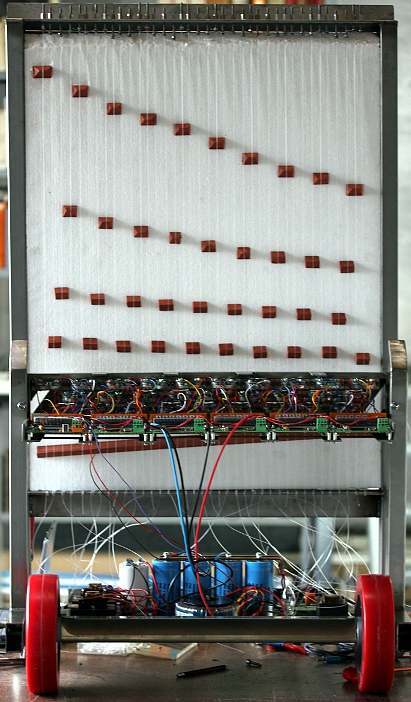
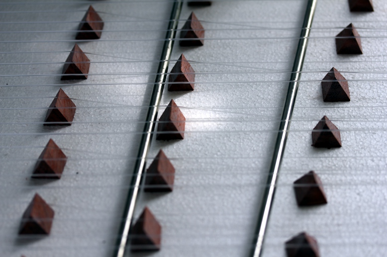
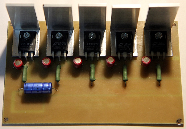
Pictures taken during the construction in our workshop (in chronological order):

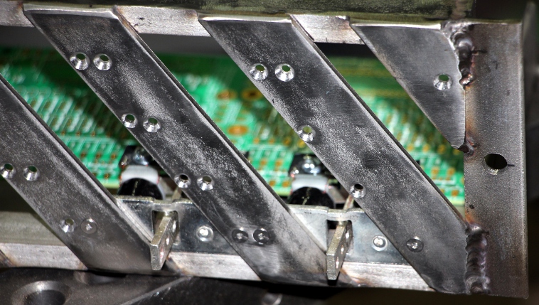


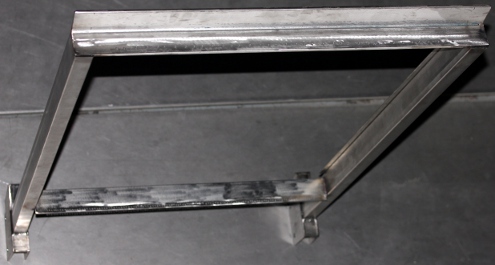

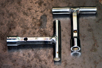
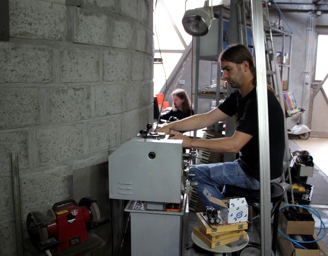


Construction & Research Diary:
- 01.03.2009: Purchase of a Zither on the Ghent flea market.
- 03.03.2009: We were donated no less than 1500 telephone relays... Examining
wether or not these could be used in the automation of Zi.
- 09.03.2009: Prototypes assembled using some 36 relays, with welded-on beaters.
Operation is sluggish and mechanically unreliable.
- 03.04.2010: Experiments with bidirectional solenoid driven pluckers. They
take up too much space, but do indeed work quite well.
- 19.12.2013: Experiments with Maxon DC motors, diameter 10mm and 13mm. This
works fine, although the mechanics for making this work reliably on an existing
Zither may become pretty complex and difficult in allignment.
- 20.12.2013: Project postponed. We first have to do <Rodo>...
- 13.05.2014: Bidirectional solenoid prototype prepared as plucking mechanism.
 This is a modification of an August Laukhuff part used for registration knobs
on pipe-organs (Catalogue nr. 3 002 00). The original manufacturer appeared
to be Syndyne, and after checking their
catalogue it became apparent that we could also get these parts without
an angled anchor. We ought to proceed a bit faster with this design as we
are urged to do so by 'De Centrale', who commissioned it for a collaborative
project with Adullah Abdulrasol.
- 14.05.2014: Syndyne contacted for custom made bidirectional solenoids. As
we plan to use pulse/hold boards for this instrument, we estimate that the
hold voltage should be no higher than 6 Volts, whereas the pulse voltage may
be very well be risen to 60 Volt. This ought to give a good range for the
velocity control. Plucking tests performed on a balalaika. In fact with just
3 pluckers we could automate the balalaika but there is not enough space on
the neck to accomodate the required solenoids for the frets.
- 15.05.2014: Construction drawings for the complete plucker mechanism. Sketches
for the tuning mechanism: we consider using mandolin tuning pegs in rows of
four.
- 16.05.2014: Mandolin-banjo rebuild with a styrofoam soundboard. This indeed
works very well.
- 19.05.2014: Experimental construction of a subminiature string plucker using
a Maxxon motor. To be evaluated.
- 27.05.2014: Still awaiting news from Syndyne...
- 01.06.2014: Definitive order placed at Syndyne for 50 solenoid assemblies.
In the meantime, starting construction of <Rumo>...
- 25.06.2014: The solenoid assemblies from Syndyne came flowing in. Construction
of the plucker mechanism can be started.
 Welding
plan drawn out.
- 26.06.2014: Welding of the plucker chassis and start drilling of the mounting
holes.

- 27.06.2014: Further work on the plucking mechanism: cutting unneeded parts
from the Syndyne assemblies. Finishing drilling work of the holes. Countersinking
all holes for M3 bolts. Design of a carrier for the six PC boards. These board
will be mounted in a horizontal plane, for ease of maintenance and programming.


- 28.06.2014: Finishing all welding on the plucker chassis.
 . A box full of 6V bulbs with E14 fittings found on a street flea market here
in Ghent.
- 30.06.2014: Start coding of the PIC firmware, as the complete plucking mechanism
has to be up and working before we can go on making the actual zither. Version
1.0 of the firmware ready to be tested. Starting implementation of testcode
in GMT. Board 1 wired, soldered and programmed.
- 01.07.2014: Further soldering works on the boards, no less than 252 MOSFETS
to be soldered... Mounting of the solenoid assemblies on the chassis done
by Mattias Parent.
- 02.07.2014: Continuing soldering works of the boards... Construction of
the red copper power rails. Mapping error in the lookup tables found and repaired.
Measurement of the loop-speed of our firmware under no-midi input conditions:
4 microseconds. Wiith no midi coming in, the square wave frequency measured
at a bit-toggling port (RA4) is 125kHz. Hence the idle loop time is 4 microseconds.
With fast midi in, and commands for all 5 strings and lights, the loop time
becomes 7.4 microseconds. The worst case scenario would be all 5 strings on
at the same time, and thus all five timers running in the code, a scenario
in which the loop speed goes up to 12.4 microseconds. Thus, this would be
the worst case jitter to expect on the duration of the velo-pulse lengths
generated. Measurements were taken with our Tektronix TDS2024C oscilloscope.
(200MHz, 2GS/s). We can be pretty confident that our code will not miss any
commands and that the jitter will remain below 1% of the soll-values.

- 03.07.2014: M4 threaded standoffs ordered from Farnell. Start wiring of
the solenoid assemblies. Version 1.0 of the firmware for all the boards written
and programmed into the microcontrollers.

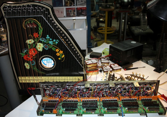
- 04.07.2014: All wiring done. Start of the first tests. As we didn't even
start making the actual stringed instrument, we perform the tests with a Zither,
placed in an upright position. We use a lab power supply adjusted to 6 V for
the hold voltage and a -36 V power supply for the negative pulse voltage.
We observe excessive bouncing of the plectrum/anchor combination. The pulse
durations have to be scaled down in the firmware.
- 05.07.2014: Firmware adjusted according to our measurements. String mapping
and therewith ambitus changed to start from midi note 40 (low E). Thus the
instrument should become reasonably compatible with the guitar. We ordered
a complete set of Dupont qanun strings. These sets come in 7 different thicknesses:
1.25 mm, 1.1 mm, 1mm, 0.9mm, 0.8 mm, 0.75 mm, 0.65 mm. Sets of banjo strings
would be a good alternative.
- 06.07.2014: Designing a new tuning mechanism, as our experiments with using
mandolin tuning screws turned out badly. Start construction of the required
power supplies. A first prototype of a tuning mechanism was constructed, starting
from a stainless steel M4 x 50 bolt.
 With
such tuning pegs, it would be imaginable to give the instruments two strings
for each note, as space requirements are really minimal. Another consequence
of using such tuning pegs is that it will lead to a pure rectangular soundboard
and instrument instead of the usual trapezoidal shape. It is mandatory that
the tuning pegs are fully in line with the strings. Giving the upper part
a staircase shape would be possible but involves a lot of welding and cutting
work.
- 07.07.2014: Calculation and design of the power supplies.
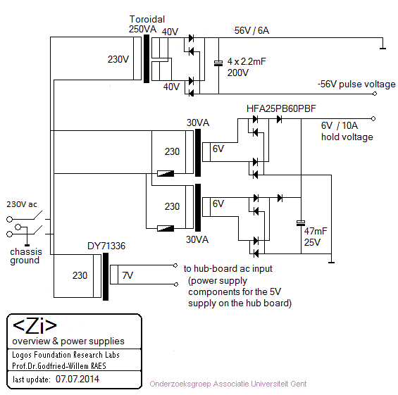 This will be mounted on the bottom plate, 500 mm wide.
- 08.07.2014: Construction of the tuning pegs explained to Mattias such that
he can prepare a full set. Start construction of the power supply assembly.
- 09.07.2014: Heavy electrolitic capacitors came flowing in. Construction
of the power supply can continue.
- 11.07.2014: Further work on the power supply and bottom chassis, including
a midi-hub board. A full day of drawing, drilling and milling on the bottom
plate. Wiring will be for tomorrow...
- 12.07.2014: Wiring the power supply unit. After testing, it came out that
the two assumed 'identical' 6V transformers (indeed, a former Radio Shack
product...) give very different output voltages: 6.7V and 8.8V... This may
cause trouble. To be checked. This is what the power supply assembly looks
like:

- 14.07.2014: Midi-hub board soldered. So now we have the required +5V available
and thus testing can continue.
- 26.07.2014: A full set of Qanun strings, ordered from Turkey, came in.
- 01.08.2014: Work on <Zi> taken up again. On connecting the new power
supply something seems to go very wrong... the negative power source draws
high current and the mosfets became extremely hot... Did we cause a short
somewhere? Apparently we had a short on the power buslines under the boards.
But also, we have to check the P-channel mosfets: BS250 cannot be used as
they have a maximum Vds voltage of only -45V. The BSP254A allows up to -250V.
ref.: datasheet.
- 02.08.2014: Further research into the origin of the fault condition, Failure
traced: the negative going power mosfet, gets Vgs > > 20V and thus the
gate of the mosfet melts down. This made us discover a general flaw in our
pulse/hold designs so far.
- 03.08.2014: Measurement circuit build up to verify our hypothesis. In future
circuits we need a voltage divider and a zener protection diode to the gate
of the velo-driver mosfet. If we use IRL640, the zener diode should be rated
for 10V. A IRF540 can also be used, and needs a zener with a voltage value
between 10 and 20V. Also the P-channel mosfet must be BSP254A. Boards 2, 3,
4, 5, 6: all IRL640 replaced with IRF540. On board 4 we soldered 14 Zenerdiodes.
As long as the negative voltage doesn't get much larger than -48V, the existing
unmodified circuit works well.
- 04.08.2014: As on board 1 none of the IRL640 were defective, we just added
gate protection zener diodes 6V2 on the solder side of the PC board. So, at
this point only boards 1 and 4 are protected with Zener diodes. All boards
mounted again in the plucker assembly. Test code in GMT adapted such that
we can test each board individualy.
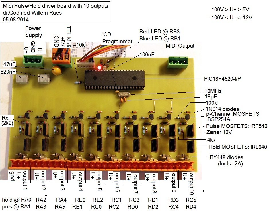
- 05.08.2014: As we want to avoid having to unsolder that many mosfets again,
we designed and build an experimenting board for tests, measurements and evaluation:
- 06.08.2014: Tests with different plectrums and materials that can be used
as plectrums. Design of a new laboratory power supply with high current and
high voltage range. It should withstand highly inductive loads, this not being
the case for commercially available laboratory power supplies...
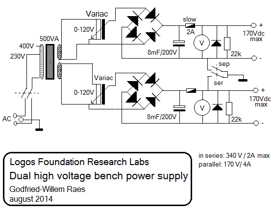
- 09.08.2014: Here is a link to our
app note for this new hefty power supply. The circuit diagram looks like
this:
- 10.08.2014: We also designed and a more universal pulse/hold board with
12 outputs, so enough for a musical octave if applied to player pianos and
organs. Here is the PCB design:
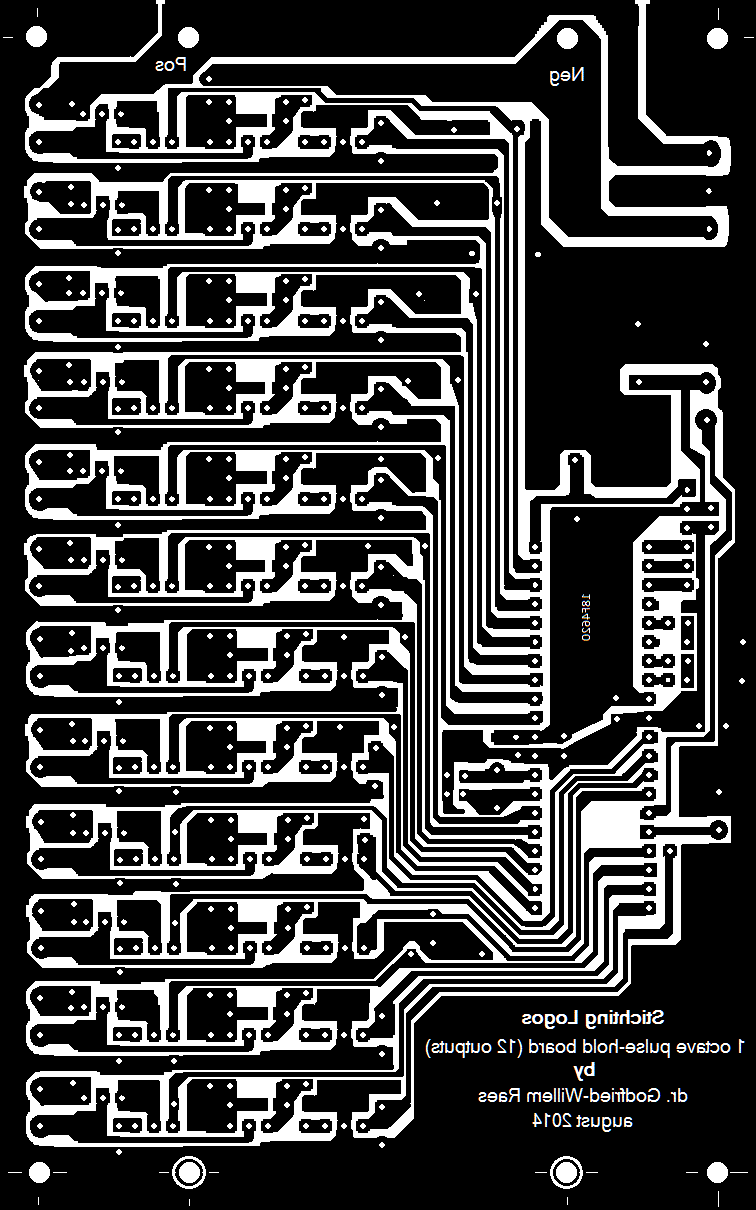 This design should be reduced to 50% for production on a PC board. The diodes
used are U12C020A types: dual diodes in TO220 housing with a common anode.
Here is their data
sheet. The hold-mosfets are IRL640 and the velo mosfets IRF540. Note that
we produced these boards only for research reasons, not withstanding that
they may replace existing designs at some point.
- 11.08.2014: Construction of a 500
Watt dual power supply, required for testing our circuitry.
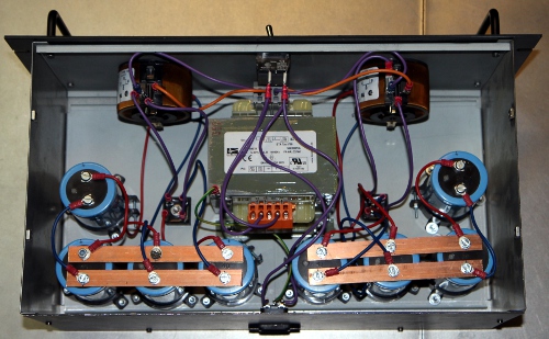
- 12.08.2014: Board 2, 3, 5,6: 10V zener diodes soldered on board. Powered
up with the high negative voltage (60V) ... smoke stacks from board 4. Whats
the matter now? Again a Mosfet gone to heaven.
- 13.08.2014: Finally... we got all boards and all pluckers to work well electrically
and on -60V. For future designs though it might be better to considers IGBT's.
For now all velo MOSFETS are IRF540. All zener diodes are 10V. We upgraded
our article on 'Expression control
in automated instruments' with our new findings. Drawing of the wheel
base and the mounting of the plucker assembly. Cutting and drilling work on
the parts. Preliminary mounting of the back wheels, building height 80 mm.
- 14.08.2014: Start construction of the wheelbase. Precision TIG-welding works
on the welding table, as sizing erors have to be kept below 1 mm. By the end
of the day, the chariot and the plucker holder are finished. Power supply
mounting works o.k., just two M6 bolt hold it in place, as the assembly slides
over the wheel spindle.
 The 'harp' will be constructed such that it is a detachable and exchangeabe
part. This makes is possible to fit a harp with twice as long strings and
thus sounding an octave lower, or exchanging it for one with steel strings...
Anyhow we will start-off by designing and making a 'harp' of the smallest
possible sizing: longest string = 650 mm (sounding length).
- 15.08.2014: Start construction of the zither properly speaking. Width between
vertical poles: 623 mm. Tuning peg holder: Aisi 304, L- 50x50, length 683
mm. String holder underside: length 623 mm. The vertical poles will be cut
from 30 x 50 profile, 1000 mm high. All holes on the string holder profile
drilled (3 mm holes).
- 24.08.2014: Tuning peg holder drilled. Vertical poles cut out. Main frame
for the harp welded together.
- 25.08.2014: Mounting feet for the harp designed and cut out.
 These must allow for a 20 mm slide to make adjustment of the strings with
the pluckers easier.
  Big
mistake: we welded one of these feet in the wrong direction... we will have
to saw it off and start again...
- 26.08.2014: Welding the feet on the harp.
 Mounting
test. We may need to add M10 setscrews on the 10 mm thick base plate of the
feet. First cut out of a sound board in expanded polystyrene. First experiments
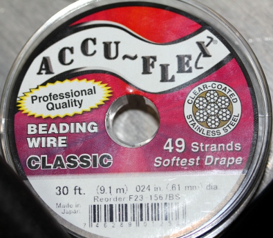
with strings, using stranded beading wire. This sounds very good, a bit banjo
like.
 Although we will not use this as string material, this stranded beading wire
really sounds excellent. Here is a picture of the rolls on which it is sold:
- 27.08.2014: First attempts to mount real Qanun strings. There are some problems
with the tuning however, as many sources are confused with regard to the octave
position of the notes. We asked Xavier Verhelst to do some research: http://www.georgedimitrisawa.com/qanun.html
(link does not work anymore) this source quotes 26 sets of triple strings
with a range of 3 octaves and a fifth, from G (midi 41), an octave and a fourth
below middle C, to D (midi 86), 2 octaves and a second above middle C. Clearly
wrong as G ought to be midi note 43. A second source, http://en.wikipedia.org/wiki/Qanun_(instrument)
states: Qanuns used in Turkey have 26 courses of strings, with three strings
per course. It is played on the lap by plucking the strings with two tortoise-shell
picks, one in each hand, or by the fingernails, and has a range of three and
a half octaves, from A2 (midi 33) to E6 (midi 76). The dimensions of Turkish
kanuns are typically 95 to 100 cm (37-39") long, 38 to 40 cm (15-16") wide
and 4 to 6 cm (1.5-2.3") high. However, this seems very unlikely, and probably
everything should be an octave up. A thirth source is: http://www.loc.gov/item/afccc.a4243b1
(link does not work anymore) audio file (wav & mp3) with the tuning (Armenia,
1937). Further at http://tribes.tribe.net/quanoun/thread/a52eb103-ee1f-4281-a167-8513f86701ea
(link does not work anymore) where a user thought that the lowest note given,
D (midi 38) ought to be G ( midi 41). The source http://www.atlasensemble.nl/assets/files/instruments/Qanun/Qanun%20by%20Bassem%20Alkhouri.pdfgives
G2 (midi 31) to D6 (midi 74), but in our opinion this also is an octave wrong,
a very common mistake amongst guitarists... So we tried out a tuning
starting from midi 50 (D) for the lowest note. This leads to following ambitus:

- 28.08.2014: As the stringing can be changed by the users, we decided to
implement a controller to set the tuning. This avoids having to use the robot
as a transposing instrument. It requires a revision of the firmware for all
6 microcontrollers though.
- 29.08.2014: First set of 11 strings mounted on the instrument. Bridges sawn
out, starting from a collection of folk guitar bridges we had in stock. The
inlay in hard plastic can be used for height adjustement of the individual
strings.
- 30.08.2014: Tube keys 7 mm purchased to make a tuning key for the instrument.
It appears that the styrofoam bends too much under the force of the strings,
making the tuning very unstable. So we will need to add a reinforcing bar
on the backside. Also the bridges need to have a larger bottom surface.
- 31.08.2014: All strings taken off again in order to make it possible to
weld two 683x30x30 mm, 3 mm thick T profiles on the backside, preventing the
polystyrene from bending too much.
- 01.09.2014: 22 Strings mounted. 20 new bridges made from hardwood. 16 more
tuning pegs to be made on the lathe.
- 02.09.2014: We made a string order mistake. Twelve strings have to be taken
off and replaced. Here is what it should be (double checked...):
 Mattias Parent called in to help us out removing and replacing the strings.
 More tuning pegs made
on the lathe. By the end of the day, all strings mounted.
  Two
tuning key made, starting from Beta tubular keys 6/7mm. These had to be hollowed
out with a 4 mm hole, at least 50 mm deep.
  Left
to be done: definitive bridges, construction, placement, adjustment. On the
picture, our experiments with different shapes and models of bridges can be
seen. Here is a detail of the tuning pegs:
 And this shows the knotting of the strings and the lower bridge:
- 03.09.2014: First attempt to tuning all strings... a tedious job.
- 04.09.2014: All combs redone from equilaterial triangle hardwood material.
First attempt to assemble the complete instrument, by bringing the harp in
front of the plucker mechanism. Now the mounting and cutting of the pluckers
can start off.

- 05.09.2014: If we want to get the effect of a triple strung instrument,
we might consider to realize this electronically. By picking up the sound
(triggered by a note-on command) and delaying it 20ms or so and sending it
back two times - with some phase shift- after amplification to a contact-driver
mounted on the soundboard, it would become possible. This entails the addition
of an ARM processor though, unless we went for analogue bucket brigade delay
lines. These electronics cound find a place on the backside of the soundboard.
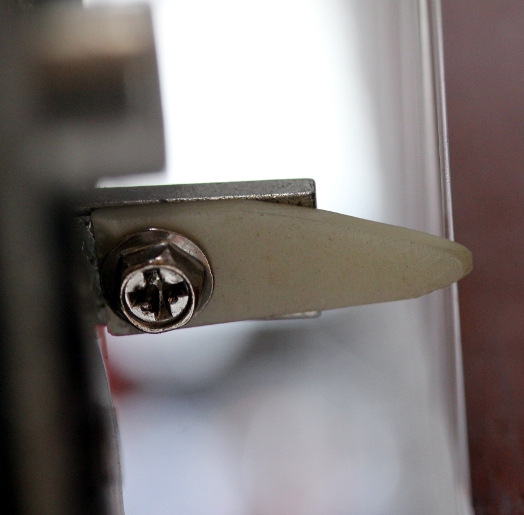
- 06-15.09.2014: Experiments and research with regard to the best plucker
shape, material and construction. The allignment promisses to become an extremely
difficult and tedious task. So far, bone material as used on guitar bridges
seems to work best.
- 16-17.09.2014: Seems that the threaded holes in the Syndyne plucker solenoids
have a non-metric #6-32 UNC thread... Obviously the corresponding bolts are
extremely hard to find on the market here... Searching through our junk packs
in an attempt to dig up some 38 #6-32 bolts... The diameter of such bolts
is 3.4 mm, so we have to enlarge the 3 mm holes in the plectra a bit.
- 18.09.2014: As we were not charmed by the sound of the highest strings,
we decided to add a bridge over them to increase the angle under which these
strings touch the sound bridges. This bridge was made from massive stainless
steel rod 8 mm thick welded on fastening plates allowing fixation on the frame
of the harp.
- 19.09.2014: As the results of the added crossbar for the highest 10 strings
were very positive, we made another crossbar for the next highest series
of ten strings. We may even add a thirth crossbar. An inconvenience is now
that if the styrofoam soundboard has to be replaced, all these crossbars need
to be unscrewed.

- 20.09.2014: All three crossbars made and mounted. The lowest one is 680
mm long, the second 690 mm and the last 700 mm.
- 21.09.2014: Threading M4 holes for the stop plates at both ends of the wheel
spindle. Stop plates mounted. These parts still need to be polished.
- 23.09.2014: Mounting of the 38 plectrums. Start adjustments...
- 24.09.2014: Works on <Zi> on hold for a while...
- 22.10.2014: The three crossbar bridges fixed with M5 x 60 bolts.
- 01.12.2014: Mounting of plectrums confined to Mattias Parent.
- 09.04.2015: Experiments performed with increased mass of the anchors in
order to increase plucking force. We can use small cube neodium magnets on
the one side, or try to obtain the equivalent through a different coding in
the firmware. We wired up a prototype board to perform these experiments.
The result were not worth the effort though.
- 23-24.04.2015: Further research and experiments by Mattias Parent.
- 25.04.2015: Board 1, output 6 velo pulse mosfet replaced as the old one
died due to a short we caused during an attempt to adjust the plucking mechanism.
- 06.08.2015: After many hours and days of experimenting we came to the conclusion
that the mechanism for the pluckers is unworkable. So we started a new design,
using linear bidirectional solenoids.
- 17.08.2015: Drawing a new design for the pluckers.
- 18-21.08.2015: Design of new electronics to be used for bidirectional solenoids.
Here is a circuit drawing:
 As the polarity of the solenoids needs to be reversed after each stroke, we
need H-bridge drivers. The old and proven L298N came to rescue here. The big
advantage of this approach is that power consumption is minimal, as no hold
current is needed anymore. However, the current for each movement is 3A! Here
is a 200% PCB for the above circuit:
  For
the solenoids we bought to be tested, we need insulating washers with a hole
of 2 mm and an outer diameter of 10 mm. Thickness around 0.5mm. This needs
some hunting, unless we can make them ourselves on the lathe.
- 22.08.2015: Plectra made from nylon staff material on the lathe. Experiments
with plucking carried out on an old zither with steel strings. The plucking
does work indeed but we notice a click-noise on each position change of the
solenoid. Seems to be unavoidable.
- 23.08.2015: Further redesign of the qanun. Considering to use the prototype
1 assembly for another robot, maybe <Tinti>,
using tiny bells... New stainless steel piece cut out to serve as a holder
for the solenoids 682mm wide, T-profile, 3mm thick. It ought to mount on the
existing carrier structure with two M8 bolts. The carrier plate for the five
new PC boards should be bolted or welded in this same bar.
- 30.09.2015: The missing and ordered bistable solenoids came in from Conrad,
so the works on the new plucker mechanism can continue.
- 02.10.2015: Helene Wolf contacted to help out with the design and cutting
of a new comb. As a cembalo maker, she ought to have the experience.
- 03.10.2015: Prototype board for the new solenoids etched, drilled and soldered.
We can test the first 8 solenoids if we have also the firmware ready. Work
for tomorrow...
- 04.10.2015: Firmware written for the first plucker board. Note repeats using
key pressure implemented. Here is the source
code.
- 05.10.2015: Photosensitive PCB's ordered from Farnell such that we can produce
the remaining four boards. Redesign of the power supply.
 The 12V transformer is clearly overdimensioned (200VA would have reached out)
but we simply had it at hand and thus decided to use it. PCB designed for
the five LT1084 regulators. The heat sinks are underdimensioned but that should
not be a problem as the supply needs only to be rated for momentary peak currents.
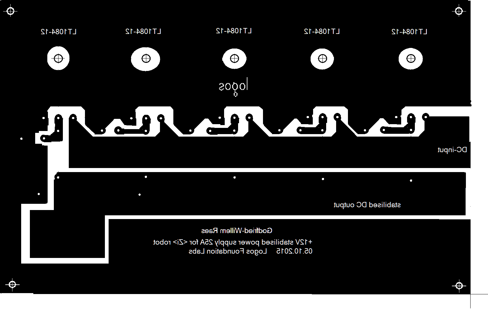 The PCB here is
at 200% and should be reduced to 50% before printing and exposing.
- 06.10.2015: Exposure, development, etching of the power supply board as
well as the four remaining solenoid driver boards. Soldering and testing of
the 25A power supply board. Mounting of the hefty 500 VA transformer and 220
mF Kemo capacitor on the bottom plate.

- 07.10.2015: Test of the 12V/25A power supply board. Found o.k.
 Drilling of the holes in the four to be done solenoid driver boards. Board
2 and soldered.
- 08.10.2015: Continuing soldering work on boards 4 and 5. Running out of
stock on some components: diodes, connectors. PCB for the driver board slightly
improved. Instead of using 8 diodes for each driver, we better use two rectifier
bridges. This change will of course only affect future production boards.

- 09.10.2015: Finalising soldering work on boards 4 and 5.
- 18.10.2015: Helene Wolf will make a new comb for <Zi>... The upper
comb:
 and the one for
underneath:
- 10.10.2015: All PCB's ready. Loading firmware for testing. Design of a carrier
board for these five PCB's. Width should be 580 mm. Reminder: distance between
the strings is and should be 15.21 mm. Here is a new drawing for the solenoid
assembly, dictating the new sizing of the strings:

- 15.10.2015: Mounting plate for the PCB's finished.
- 06.11.2015: All bidirectional solenoids glued on the T-bar with blue Loctite
gasket silicone glue. There is a half-coil offset to the left, so the plucking
will happen on the left side of the strings.
- 07.11.2015: Start wiring of the solenoids to the boards with Weidmueller
connectors.
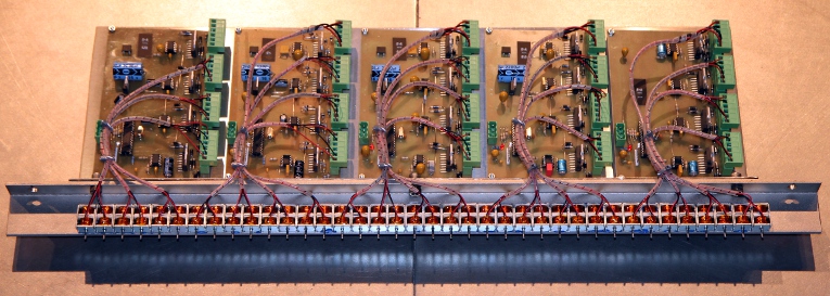
- 08.11.2015: Wiring of the midi and 5V power connectors.
 All wiring done... The re-assembly on the chassis can start.
- 09.11.2015: All boards connected to the bottom plate. Data and power connections
finished. First tests of the new hardware. GMT testcode rewritten for the
new hardware. Firmware for the five boards adapted to the newest implementation.
This be version 1.0. First testing reveals a bug on note 53 (Zi1 board) and
heating of the drivers for notes 58 to 61 (Zi2 board). As the firmware for
all PIC's is basically the same, we first will have to look for some hardware
bugs.
- 10.11.2015: Two L298 drivers replaced on board Zi2. We had a short on the
PCB on the output pins...
- 11.11.2015: Further debug sessions on the PIC firmware. Shaky behavior of
board Zi3 solved: we forgot the 10k pull up resistor on pin1 of the PIC microcontroller.
Shakyness of note 54 was due do a bad solder connection on one of the protection
diodes on board Zi1. Plucker reset controller added in the firmware. We are
now at firmware version 1.2. Now we still have a problem on board Zi1 with
note 53. Must be a hardware problem. Velo's increased a factor 2. Now at firmware
version 1.21. Testcode in GTM extended. By the end of the working day, everything
seems to be working fine, except for note 53. However we found the bug: the
inverter chip is failing. Replacement will be for tomorrow.
- 12.11.2015: 7667 bufferchip replaced and everything works fine now. We have
no idea as to what caused the 7667 to fail... infant mortality?
- 14.11.2015: Start mounting plectrums but we are falling out of M2 nuts...
Plucking test performed used a balalaika. Not very promissing...
- 16.11.2015: Fresh M2 nuts purchased at MEA. Mounting of all plectrums with
two stainless steel M2 nuts on the solenoids.
- 12-28.12.2015: Construction of a new bridge by Helene Wolf.
- 11.01.2016: Work on Zi taken up again.
- 26.01.2016: New bridges made by Helene Wolf presented and found to be excellent.
Start restringing the instrument.
- 19.02.2016: Sliding feet of the soundboard cut open again as the mechanism
was too stiff.
- 24.02.2016: Adjustment studs drilled and mounted to allow precise positioning
of the soundboard versus the plucking mechanism. For now using M6 threaded
rods, but this may become a larger size later on.
- 29.02.2016: Further restringing and gage checking. Placement of the new
bridges with Helene Wolf.
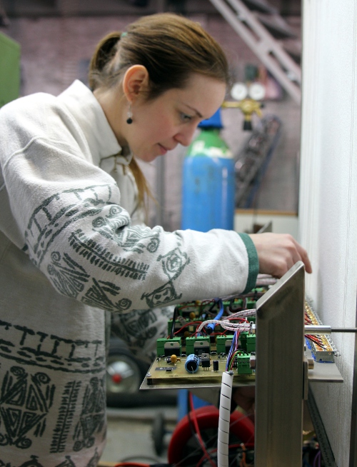 Looks
like we will have to order some spare 0.8 mm diameter Qanun string material.
- 01.03.2016: Cutting of the standing feet for the harp such that it can be
moved further backwards.
- 02.03.2016: Some adjustment required for the stand-off between harp and
plucking mechanism.
- 15.10.2016: All experiments with suitable plectrum material failed. The
problem that plagued our first and rejected design is reappearing: the solenoids
do not have enough power in the mid position. Furthermore, it appears unfeasable
to adjust the plucking distance reliably. As in top of all this bad luck,
we also lost all funding due to a bad and big-ego oboist, Piet Van Bockstal
that issued a negative and cancelling advise for funding against the Logos
Foundation. So, the project has to be placed on hold.
- 09.10.2024: <Zi> project taken up again. Considering to use linear
motors instead of solenoids. These for sure have enough power but they are
pretty slow... In principle we could use the same electronic circuits to drive
the motors. The firmware needs a complete revision and note repetitions seems
to be impossible, unless we allow only very slow repetitions...
- 10.10.2024: Two new PCB's etched and drilled.
- 11.10.2024: One board soldered. PCB lay-out improved.
- 12.10.2024: Second board soldered. Tests of the few firmware.
- 12.11.2025: Work in the zither taken up again. The very succesfull poltergeist
mechanism we made for <Ubu>, gave us the idea to use some of the hundreths
of Binder 12V solenoids we have in stock as rebounce hammers. To be successfull
we have to replace the springs with a much stronger type. The original springs
have following sizes:
 The
thread for mounting the solenoids is M10x1 (metric extra fine).
- 13.11.2025: It becomes mandatory to equip the Binder solenoids with much
stronger springs. Experiment performed: using a pressure spring (Fabory stock
item) 0.5 x 6.5 x 20, shortened to 7.5 mm (4 turns), works well with a supply
voltage of 48 V. Duty cycle should be kept smaller than 5%. Current is 240mA,
the coil resistance is 200 Ohms. Peak power follows as 11.5 Watt. For the
control we can use some older pulse-only PCB's. As there are 25 chromatic
strings, we can even save some pins for the ICD. Each board is designed for
16 outputs. Application moved to the <Zibalo>
project...
- 11.01.2026: Looks like we have to abandon the original <Zi> project
alltogether. Plucking strings sofar has been unsuccessfull... Can we use the
solenoid assembly to activate thin springs? First series of experiments carried
out.
- 12.01.2026: <Zi> fired up again. All solenoids seem to be working
fine. Springs ordered from Temu in China... <Zi> may become a completely
different robot alltogether now. Here is a link to
the new rebaptised project: <Zip>.
-
TO DO:
- Final (re)construction of the instrument
- almost everything...
Last update: 2026-02-08
by Godfried-Willem Raes
Circuit details solenoid driver boards:
The string lengths are calculated and the string gages follow those of
classical Qanun strings. We used a complete set for a 26 note diatonic Qanun
(Dupont Kanun Teli), strings from Turkey. The tables below give the speaking
lengths of the strings.
Board 1: notes 50 - 57
-
| string nr |
6-pole Weidmueller connector pins |
MIDI
mapping
|
PIC dir pin |
PIC pulse pin (enable) |
string lenght (mm) |
string diameter
|
| 1 |
A:
1,2
|
50 |
RA0 |
RA2 |
650 |
1.25
|
| 2 |
A:
5,6
|
51 |
RA1 |
RA3 |
620 |
1.25
|
| 3 |
B:
1,2
|
52 |
RA4 |
RC0 |
594 |
1.25
|
| 4 |
B:
5,6
|
53 |
RA5 |
RC1 |
571 |
1.10
|
| 5 |
C:
1,2
|
54 |
RC2 |
RC4 |
545 |
1.10
|
| 6 |
C:
5,6
|
55 |
RC3 |
RC5 |
518 |
1.10
|
| 7 |
D:
1,2
|
56 |
RB0 |
RB2 |
498 |
1.00
|
| 8 |
D:
5,6
|
57 |
RB1 |
RB3 |
476 |
1.00
|
- Source code for this board: Zi_1.bas
Board 2: notes 58 - 65-
| string nr |
6-pole Weidmueller connector pins |
MIDI
mapping
|
PIC dir pin |
PIC pulse pin (enable) |
string lenght (mm) |
string diameter
|
| 9 |
A:
1,2
|
58 |
RA0 |
RA2 |
457 |
1.00
|
| 10 |
A:
5,6
|
59 |
RA1 |
RA3 |
437 |
1.00
|
| 11 |
B:
1,2
|
60 |
RA4 |
RC0 |
419 |
1.00
|
| 12 |
B:
5,6
|
61 |
RA5 |
RC1 |
401 |
1.00
|
| 13 |
C:
1,2
|
62 |
RC2 |
RC4 |
384 |
1.00
|
| 14 |
C:
5,6
|
63 |
RC3 |
RC5 |
368 |
0.90
|
| 15 |
D:
1,2
|
64 |
RB0 |
RB2 |
353 |
0.90
|
| 16 |
D:
5,6
|
65 |
RB1 |
RB3 |
339 |
0.90
|
- Source code for this board: Zi_2.bas
Board 3: notes 66 - 73
-
| string nr |
6-pole Weidmueller connector pins |
MIDI
mapping
|
PIC dir pin |
PIC pulse pin (enable) |
string lenght (mm) |
string diameter
|
| 17 |
A:
1,2
|
66 |
RA0 |
RA2 |
324 |
0.90
|
| 18 |
A:
5,6
|
67 |
RA1 |
RA3 |
310 |
0.90
|
| 19 |
B:
1,2
|
68 |
RA4 |
RC0 |
298 |
0.90
|
| 20 |
B:
5,6
|
69 |
RA5 |
RC1 |
287 |
0.90
|
| 21 |
C:
1,2
|
70 |
RC2 |
RC4 |
275 |
0.90
|
| 22 |
C:
5,6
|
71 |
RC3 |
RC5 |
264 |
0.90
|
| 23 |
D:
1,2
|
72 |
RB0 |
RB2 |
254 |
0.80
|
| 24 |
D:
5,6
|
73 |
RB1 |
RB3 |
244 |
0.80
|
- Source code for this board: Zi_3.bas
Board 4: notes 74 - 81
-
| string nr |
6-pole Weidmueller connector pins |
MIDI
mapping
|
PIC dir pin |
PIC pulse pin (enable) |
string lenght (mm) |
string diameter
|
| 25 |
A:
1,2
|
74 |
RA0 |
RA2 |
235 |
0.80
|
| 26 |
A:
5,6
|
75 |
RA1 |
RA3 |
226 |
0.80
|
| 27 |
B:
1,2
|
76 |
RA4 |
RC0 |
217 |
0.80
|
| 28 |
B:
5,6
|
77 |
RA5 |
RC1 |
209 |
0.80
|
| 29 |
C:
1,2
|
78 |
RC2 |
RC4 |
201 |
0.80
|
| 30 |
C:
5,6
|
79 |
RC3 |
RC5 |
194 |
0.80
|
| 31 |
D:
1,2
|
80 |
RB0 |
RB2 |
187 |
0.80
|
| 32 |
D:
5,6
|
81 |
RB1 |
RB3 |
180 |
0.70
|
- Source code for this board: Zi_4.bas
Board 5: notes 82 -87-
| string nr |
6-pole Weidmueller connector pins |
MIDI
mapping
|
PIC dir pin |
PIC pulse pin (enable) |
string lenght (mm) |
string diameter
|
| 33 |
A:
1,2
|
82 |
RA0 |
RA2 |
174 |
0.70
|
| 34 |
A:
5,6
|
83 |
RA1 |
RA3 |
168 |
0.70
|
| 35 |
B:
1,2
|
84 |
RA4 |
RC0 |
162 |
0.70
|
| 36 |
B:
5,6
|
85 |
RA5 |
RC1 |
156 |
0.70
|
| 37 |
C:
1,2
|
86 |
RC2 |
RC4 |
151 |
0.70
|
| 38 |
C:
5,6
|
87 |
RC3 |
RC5 |
146 |
0.70
|
| - |
D:
1,2
|
nc |
RB0 |
RB2 |
- |
- |
| - |
D:
5,6
|
nc |
RB1 |
RB3 |
- |
- |
- Source for this board: Zi_5.bas
-
Schematic:

- PCB:

- Power supply: The PCB for the 25A/12V supply is: [scale 200%]
-
Tuning mechanism:
- Tuning keys designed by us. A special 7 mm hex tubular key with handgrip
is required for tuning.
 Mandalar
can be mounted as an option. Moving the bridges is also possible to obtain
microtonal scales. When changing a string, to not overtighten the small
M4 nut holding the string on the threaded tuning pegs. If too much force
is given here, the string will be cut off! In tuning, hold the threaded
bolt part such that it does not twist when rotating the tuning nuts.
- If ever the styrofoam soundboard needs replacement, all tuning pegs
have to be unscrewed and taken of the upper part. The harp-chassis has
to be taken off the chassis holding the pluckers. The soundboard can only
be replaced from the string side of the instrument. The crossbars through
the strings have to be removed as well. These are fixed to the frame with
M5 x 70 bolts.
- Replacing strings does not involve any demounting of any other part
than the tuning pegs themselves. To determine the exact design position
of the bridges, refer to the tables above. Of course, one can experiment
with other placements of the bridges as this affects the sound quality
of the instrument.
-
Plucking birectional solenoid or linear motor assemblies:
- Prototype 1 (rejected) : Syndyne, each coil has 28 Ohms DC resistance.
The 100% duty cycle voltage is specified as 14 V. Holding force 35 inch-g,
or 0.89 kgmm. The mounting holes on the pivoting part have an internal
#6-32 UNC thread. (Fabory order nr. for the screws: 07212.035.006).
- Prototype 2: Hubmagnet HMB-151. 001-12V DC (Conrad order nr. 541-296-04)
DC coil resistance: 4 Ohms (rejected end 2016)
- Prototype 3: DFROBOT, Type FIT0803, push rod 10 mm, 128 N. Nominal working
voltage: 6 V. (under research, 2024) Abandonned because way too slow.
Criticism:
- Although the bidirectional solenoids used for the first prototype work here,
their force is still way too low for a powerfull plucked-string sound. Thus
the velocity range possible with <Zi> using this mechanism is far below
our initial expectations. Hence the construction of a second mechanism, using
bidirectional bipolar solenoids. The clicking noise these solenoids produce
seems to be unavoidable.
- The second mechanism proved unworkable as well and was rejected again. In
2024 we started a new experiment using linear motors.
- Linear motors work, but due to their delays the timing becomes completely
unreliable, hence musically unacceptable...
- The styrofoam soundboard performs very well.
-
References:
Linear Technologies: LT1083, LT1084,
LT1085 Low dropout positive fixed voltage regulators
RAES, Godfried-Willem, "Expression
control in musical automates", 1977/2026
ROSSING, Thomas.D (editor), "The Science of String Instruments"
, ed: Springer NY, Stanford CCRMA, 2010 ISBN 978-1-4419-7109-8
SMIT, Thorsten a.o.,
'A highly accurate plucking mechanism for acoustical measurements of stringed
instruments', in: Journal of the Acoustical Society of America, EL223,
may 2010.
STMicroelectronics: Data
sheet for the L298 dual full bridge driver
STMicroelectronics: L6201-L6202-L6203
DMOS dual full bridge driver
Syndyne catalogue
Wikipedia entry on the Qanun.

Archival
Rejected version 1.0 documentation:
Power supplies:
- +5 V DC - 250 mA(Logic and microcontrollers),
- 5.8 V DC (hold voltage) 10A
- -60 V DC (pulse voltage) 6A


Circuit details solenoid driver boards:
The string lengths are calculated and the string gages follow those of classical
Qanun strings. We used a complete set for a 26 note diatonic Qanun (Dupont Kanun
Teli), strings from Turkey.
Board 1:
| string nr |
board output |
connector pin |
mapping |
remarks |
PIC pulse pin |
PIC hold pin |
string lenght (mm) |
string diameter
|
| - |
1 |
2 |
note 120 |
hold only - lite |
4 = RA1 |
3 = RA2 |
|
|
| - |
2 |
3 |
note 121 |
hold only - lite |
2 = RA3 |
5 = RA0 |
|
|
| - |
3 |
4 |
nc |
nc (broken) |
6 = RA5 |
7 = RA4 (*) |
|
|
| - |
4 |
5 |
nc |
nc |
9 = RE1 |
8 = RE0 |
|
|
| 1 |
5 |
7 |
50 |
left |
37 = RB4 |
10 = RE2 |
650 |
1.25
|
| 1 |
6 |
8 |
|
right |
35 = RB2 |
36 = RB3 |
|
|
| 2 |
7 |
9 |
78 |
left |
33 = RB0 |
34 = RB1 |
201 |
0.80
|
| 2 |
8 |
10 |
|
right |
29 = RD6 |
30 = RD7 |
|
|
| 3 |
9 |
12 |
69 |
left |
27 = RD4 |
28 = RD5 |
287 |
0.90
|
| 3 |
10 |
13 |
|
right |
23 = RC4 |
24 = RC5 |
|
|
| 4 |
11 |
14 |
60 |
left |
21 = RD2 |
22 = RD3 |
419 |
1.00
|
| 4 |
12 |
15 |
|
right |
16 = RC1 |
15 = RC0 |
|
|
| 5 |
13 |
17 |
51 |
left |
18 = RC3 |
17 = RC2 |
620 |
1.25
|
| 5 |
14 |
18 |
|
right |
20 = RD1 |
19 = RD0 |
|
|
This board uses BYV27 diodes in the hold-circuit. On the other 5 boards we
used MUR4100 types. The double diodes are invariably BYV32 types. These are
only mounted on outputs meant to switch inductive loads. The P-channel Mosfets
are BSP254A types and the power Mosfets all IRL640. On this board pin RA5 is
programmed to be used as a loopspeed measurement output. The pin can be accessed
on the gate connection of the hold mosfet, not mounted on the board. Weidmueller
connector pins 1,6,11,16, 19 are connected to the positive hold voltage on all
boards (+6 V).
The source code for the 18F4620 processor
on this board can be downloaded here.
Board 2:
| string nr |
board output |
connector pin |
mapping |
remarks |
PIC hold pin |
PIC pulse pin |
string length (mm)
|
string diameter
|
| 6 |
1 |
2 |
79 |
left |
4 = RA2 |
3 = RA1 |
194 |
0.80
|
| 6 |
2 |
3 |
|
right |
2 = RA0 |
5 = RA3 |
|
|
| 7 |
3 |
4 |
70 |
left |
6 = RA4 |
7 = RA5 |
275 |
0.90
|
| 7 |
4 |
5 |
|
right |
8 = RE0 |
9 = RE1 |
|
|
| 8 |
5 |
7 |
61 |
left |
10 = RE2 |
37 = RB4 |
401 |
1.00
|
| 8 |
6 |
8 |
|
right |
36 = RB3 |
35 = RB2 |
|
|
| 9 |
7 |
9 |
52 |
left |
34 = RB1 |
33 = RB0 |
594 |
1.25
|
| 9 |
8 |
10 |
|
right |
30 = RD7 |
29 = RD6 |
|
|
| 10 |
9 |
12 |
80 |
left |
28 = RD5 |
27 = RD4 |
187 |
0.80
|
| 10 |
10 |
13 |
|
right |
24 = RC5 |
23 = RC4 |
|
|
| 11 |
11 |
14 |
71 |
left |
22 = RD3 |
21 = RD2 |
264 |
0.90
|
| 11 |
12 |
15 |
|
right |
15 = RC0 |
16 = RC1 |
|
|
| 12 |
13 |
17 |
62 |
left |
17 = RC2 |
18 = RC3 |
384 |
1.00
|
| 12 |
14 |
18 |
|
right |
19 = RD0 |
20 = RD1 |
|
|
The source code for the 18F4620 processor
on this board can be downloaded here.
Board 3:
| string nr |
board output |
connector pin |
mapping |
remarks |
PIC hold pin |
PIC pulse pin |
string length (mm) |
string diameter
|
| 13 |
1 |
2 |
53 |
left |
4 = RA2 |
3 = RA1 |
571 |
1.10
|
| 13 |
2 |
3 |
|
right |
2 = RA0 |
5 = RA3 |
|
|
| 14 |
3 |
4 |
81 |
left |
6 = RA4 |
7 = RA5 |
180 |
0.70
|
| 14 |
4 |
5 |
|
right |
8 = RE0 |
9 = RE1 |
|
|
| 15 |
5 |
7 |
72 |
left |
10 = RE2 |
37 = RB4 |
254 |
0.80
|
| 15 |
6 |
8 |
|
right |
36 = RB3 |
35 = RB2 |
|
|
| 16 |
7 |
9 |
63 |
left |
34 = RB1 |
33 = RB0 |
368 |
0.90
|
| 16 |
8 |
10 |
|
right |
30 = RD7 |
29 = RD6 |
|
|
| 17 |
9 |
12 |
54 |
left |
28 = RD5 |
27 = RD4 |
545 |
1.10
|
| 17 |
10 |
13 |
|
right |
24 = RC5 |
23 = RC4 |
|
|
| 18 |
11 |
14 |
82 |
left |
22 = RD3 |
21 = RD2 |
174 |
0.70
|
| 18 |
12 |
15 |
|
right |
15 = RC0 |
16 = RC1 |
|
|
| 19 |
13 |
17 |
73 |
left |
17 = RC2 |
18 = RC3 |
244 |
0.80
|
| 19 |
14 |
18 |
|
right |
19 = RD0 |
20 = RD1 |
|
|
The source code for the 18F4620 processor
on this board can be downloaded here.
Board 4:
| string nr |
board output |
connector pin |
mapping |
remarks |
PIC hold pin |
PIC pulse pin |
string length (mm) |
string diameter
|
| 20 |
1 |
2 |
64 |
left |
4 = RA2 |
3 = RA1 |
353 |
0.90
|
| 20 |
2 |
3 |
|
right |
2 = RA0 |
5 = RA3 |
|
|
| 21 |
3 |
4 |
55 |
left |
6 = RA4 |
7 = RA5 |
518 |
1.10
|
| 21 |
4 |
5 |
|
right |
8 = RE0 |
9 = RE1 |
|
|
| 22 |
5 |
7 |
83 |
left |
10 = RE2 |
37 = RB4 |
168 |
0.70
|
| 22 |
6 |
8 |
|
right |
36 = RB3 |
35 = RB2 |
|
|
| 23 |
7 |
9 |
74 |
left |
34 = RB1 |
33 = RB0 |
235 |
0.80
|
| 23 |
8 |
10 |
|
right |
30 = RD7 |
29 = RD6 |
|
|
| 24 |
9 |
12 |
65 |
left |
28 = RD5 |
27 = RD4 |
339 |
0.90
|
| 24 |
10 |
13 |
|
right |
24 = RC5 |
23 = RC4 |
|
|
| 25 |
11 |
14 |
56 |
left |
22 = RD3 |
21 = RD2 |
498 |
1.00
|
| 25 |
12 |
15 |
|
right |
15 = RC0 |
16 = RC1 |
|
|
| 26 |
13 |
17 |
84 |
left |
17 = RC2 |
18 = RC3 |
162 |
0.70
|
| 26 |
14 |
18 |
|
right |
19 = RD0 |
20 = RD1 |
|
|
The source code for the 18F4620 processor
on this board can be downloaded here.
Board 5:
| string nr |
board output |
connector pin |
mapping |
remarks |
PIC hold pin |
PIC pulse pin |
string length (mm) |
string diameter
|
| 27 |
1 |
2 |
75 |
left |
4 = RA2 |
3 = RA1 |
226 |
0.80
|
| 27 |
2 |
3 |
|
right |
2 = RA0 |
5 = RA3 |
|
|
| 28 |
3 |
4 |
66 |
left |
6 = RA4 |
7 = RA5 |
324 |
0.90
|
| 28 |
4 |
5 |
|
right |
8 = RE0 |
9 = RE1 |
|
|
| 29 |
5 |
7 |
57 |
left |
10 = RE2 |
37 = RB4 |
476 |
1.00
|
| 29 |
6 |
8 |
|
right |
36 = RB3 |
35 = RB2 |
|
|
| 30 |
7 |
9 |
85 |
left |
34 = RB1 |
33 = RB0 |
156 |
0.70
|
| 30 |
8 |
10 |
|
right |
30 = RD7 |
29 = RD6 |
|
|
| 31 |
9 |
12 |
76 |
left |
28 = RD5 |
27 = RD4 |
217 |
0.80
|
| 31 |
10 |
13 |
|
right |
24 = RC5 |
23 = RC4 |
|
|
| 32 |
11 |
14 |
67 |
left |
22 = RD3 |
21 = RD2 |
310 |
0.90
|
| 32 |
12 |
15 |
|
right |
15 = RC0 |
16 = RC1 |
|
|
| 33 |
13 |
17 |
58 |
left |
17 = RC2 |
18 = RC3 |
457 |
1.00
|
| 33 |
14 |
18 |
|
right |
19 = RD0 |
20 = RD1 |
|
|
The source code for the 18F4620 processor
on this board can be downloaded here.
Board 6:
| string nr |
board output |
connector pin |
mapping |
remarks |
PIC hold pin |
PIC pulse pin |
string length |
string diameter
|
| 34 |
1 |
2 |
86 |
left |
4 = RA2 |
3 = RA1 |
151 |
0.70
|
| 34 |
2 |
3 |
|
right |
2 = RA0 |
5 = RA3 |
|
|
| 35 |
3 |
4 |
77 |
left |
6 = RA4 |
7 = RA5 |
209 |
0.80
|
| 35 |
4 |
5 |
|
right |
8 = RE0 |
9 = RE1 |
|
|
| 36 |
5 |
7 |
68 |
left |
10 = RE2 |
37 = RB4 |
298 |
0.90
|
| 36 |
6 |
8 |
|
right |
36 = RB3 |
35 = RB2 |
|
|
| 37 |
7 |
9 |
59 |
left |
34 = RB1 |
33 = RB0 |
437 |
1.00
|
| 37 |
8 |
10 |
|
right |
30 = RD7 |
29 = RD6 |
|
|
| 38 |
9 |
12 |
87 |
left |
28 = RD5 |
27 = RD4 |
146 |
0.70
|
| 38 |
10 |
13 |
|
right |
24 = RC5 |
23 = RC4 |
|
|
| - |
11 |
14 |
nc |
nc |
22 = RD3 |
21 = RD2 |
|
|
| - |
12 |
15 |
nc |
nc |
15 = RC0 |
16 = RC1 |
|
|
| - |
13 |
17 |
122 |
hold only - lite |
17 = RC2 |
18 = RC3 |
|
|
| - |
14 |
18 |
123 |
hold only -lite |
19 = RD0 |
20 = RD1 |
|
|
The source code for the 18F4620 processor
on this board can be downloaded here.
This board does not have the pulse Mosfets nor the double diodes in the four
right-most outputs.
Schematic: 
Plucking birectional solenoid assemblies:
- Prototype 1 (rejected) : Syndyne, each coil has 28 Ohms DC resistance. The
100% duty cycle voltage is specified as 14 V. Holding force 35 inch-g, or
0.89 kgmm. The mounting holes on the pivoting part have an internal #6-32
UNC thread. (Fabory order nr. for the screws: 07212.035.006).
(This assembly was later used for our <Tinti> robot.)
- Prototype 2: bipolar bidirectional solenoids. Nominal working voltage 12V.
Coil resistance: 4 Ohms. (This assembly was finally used for the <Zip>
robot.)

These
components are normally used as register knobs on pipe organs with electromagnetic
registration. We contacted the factory in order to obtain these components with
a straight anchor, as this would be much easier to attach the plectra. If we
use four rows of pluckers, and using a somewhat weird order of strings it appeared
possible to design the zither with a string distance of 15 mm. So for a 3 octave
instrument, the width could be limited to ca. 60 cm. We made a plucker assembly
for a maximum of 38 strings, welded from stainless steel. The electronics require
twice as many pulse/hold circuits and thus we needed no less than six driver
boards and microprocessors. These boards are the same as the ones we developed
for <Qt>, <Bomi> and a few more robots where velocity control combined
with a hold function was needed. The boards have a maximum of 14 outputs each
and taking into acount that here we need two outputs for each string, we need
one board for every seven strings. The strange order of the strings was caused
by the design rule dictating the strings to be plucked at about 1/7th of their
lenght.
The picture
shows the plucker mechanism with associated electronics before wiring.


 The string gages used as well as the sounding string lenghts are given in the
table.
  Five
of these boards are required for the complete qanun. The power requirements
are a lot more relaxed as compared to the first prototype design. This mainly
because of the pulse-only operation of the solenoids. However, these solenoids
having a DC resistance of only 4.2 Ohms, draw a pulse current of 2.8A each,
which is at the limit of what the L298 drivers can cope with. The data sheet
specifies a maximum of 3A, non repetitive pulse. The pulses being limited to
maximum 50ms with a 50% duty cycle relaxes the limits though. Unfortunately
there is as yet no integrated mosfet H-bridge on the market with a wider range.
As to the power supply, a 12V / 500VA transformer and some parallelled LT1024-12V
regulators seemed adequate. Here is a picture of these solenoids:
  This is the ambitus for the instrument when using a complete set of Qanun strings.
This also is the ambitus as implemented in MIDI.
  To reach this ambitus, guitar strings can be used. Obviously, if other strings
are used, other tunings are certainly possible. The instrument would than behave
as a transposing instrument and should be treated accordingly. The lowest note
in the original design (40), low E corresponds to the lowest note on the guitar
and will apply if the instrument is strung with guitar strings. As to
the Qanun, there is no real standard for the ambitus of the traditional Qanun,
although midi 50 (D) to 93 (a''), diatonic, is commonly found in Turkey.

 This will be mounted on the bottom plate, 500 mm wide.
 This design should be reduced to 50% for production on a PC board. The diodes
used are U12C020A types: dual diodes in TO220 housing with a common anode.
Here is their data
sheet. The hold-mosfets are IRL640 and the velo mosfets IRF540. Note that
we produced these boards only for research reasons, not withstanding that
they may replace existing designs at some point.
 Mattias Parent called in to help us out removing and replacing the strings.
 As the polarity of the solenoids needs to be reversed after each stroke, we
need H-bridge drivers. The old and proven L298N came to rescue here. The big
advantage of this approach is that power consumption is minimal, as no hold
current is needed anymore. However, the current for each movement is 3A! Here
is a 200% PCB for the above circuit:
  For
the solenoids we bought to be tested, we need insulating washers with a hole
of 2 mm and an outer diameter of 10 mm. Thickness around 0.5mm. This needs
some hunting, unless we can make them ourselves on the lathe.
 The 12V transformer is clearly overdimensioned (200VA would have reached out)
but we simply had it at hand and thus decided to use it. PCB designed for
the five LT1084 regulators. The heat sinks are underdimensioned but that should
not be a problem as the supply needs only to be rated for momentary peak currents.
 The PCB here is
at 200% and should be reduced to 50% before printing and exposing.

 The
thread for mounting the solenoids is M10x1 (metric extra fine).


