<Pi>
<¶>
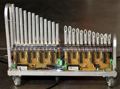
an experimental extreme high pitched electroacoustic pipe organ using
buzzer driven pipes
Godfried-Willem Raes
2017
|
<Pi> <¶>
|
<Pi>
A modern times serinette this little automated instrument could be called.
It's indeed very small and really portable. In the last couple of years we were
asked very often to deliver lectures on our work in musical robotics all over
the world. It was always frustrating that we couldn't demonstrate any of them
at these occasions, as none of the robots in the orchestra can be taken as hand
luggage on an airplane. A miniature could come to rescue here. However, the
idea for this tiny robot grew indirectly from a project we were involved in
by Laura Maes. She needed hundredths of little circuits producing nothing but
very short spikes, Here is a
link. That project lead us to a period of quite intensive research into
very small and cheap sound producing devices. One of the devices we thus ran
into was a tiny electromagnetic buzzer, type ABT-408-RC costing only about one
Euro a piece. The useful frequency response of these devices, although far from
linear, ranges from ca. 920 Hz to over 8000Hz. Here
is the datasheet. Curious as we are, we could not resist disassembling one
of these buzzers. They are build up with a 2 mm diameter permanent magnet on
which a coil is wound.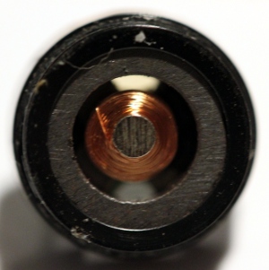 A 11.2 mm diameter membrane made from 0.05 mm thin steel and with a center part
diameter 4 mm doubling the thickness and spot welded on, mounted at close proximity
to the magnet, makes the sound source.
A 11.2 mm diameter membrane made from 0.05 mm thin steel and with a center part
diameter 4 mm doubling the thickness and spot welded on, mounted at close proximity
to the magnet, makes the sound source. 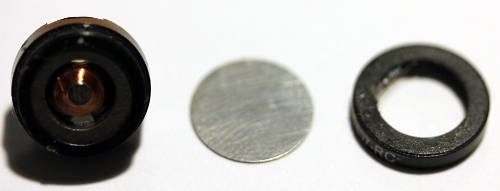 On
the backside next to the contacts, there are two venting holes. We designed
resonator tubes made from aluminum pipe 10 mm outer diameter, 8 mm inner diameter.
The sound opening of the buzzers is rectangular and thus we had to bring the
connecting end of the tubes in shape to match the opening. A special extruding
tool was made to this end. The sound of the pipes thus formed is quite reedy,
as was to be be expected from metal membranes, and thus compares quite well
to a high pitched regal. For the seven top notes (midi 120-127) we had to use
different buzzers as the sound pressure level of the ABT-408's was too low in
the range 8000 to 12500 Hz.
On
the backside next to the contacts, there are two venting holes. We designed
resonator tubes made from aluminum pipe 10 mm outer diameter, 8 mm inner diameter.
The sound opening of the buzzers is rectangular and thus we had to bring the
connecting end of the tubes in shape to match the opening. A special extruding
tool was made to this end. The sound of the pipes thus formed is quite reedy,
as was to be be expected from metal membranes, and thus compares quite well
to a high pitched regal. For the seven top notes (midi 120-127) we had to use
different buzzers as the sound pressure level of the ABT-408's was too low in
the range 8000 to 12500 Hz.
For driving the buzzers we designed a circuit build around the microchip 24EP128MC202 microprocessor. One of these chips can serve 3 pitches. All sound synthesis is handled in the digital domain using PWM techniques. This is very different than the hybrid digital-analog approach we used in building the <Hybr>-series of robots. Also, in this approach, building cost is quite a bit lower than in those earlier designs using expensive analogue components. On each processor chip, three timers are used to generate the required pitches with variable duty cycles. The three PWM channels working at a base frequency of >300kHz are used for the envelope control of each individual note by multiplying their output with the variable duty cycle square wave signal from the tone generators. No low pass filtering was applied, as all possible artifacts are situated well above the normal auditory perception range. Moreover, the coils driving the membranes serve as an intrinsic low pass filter due to their inductance (900uH). We considered using analog control for the global volume control of the instrument as the power supply voltage for the buzzers controls directly the sound volume leading to a possibly better resolution in dynamics. However, after some experiments we dropped the idea mainly because it would introduce a high risk of overloading the buzzers if the instrument were given in the hands of not knowledgeable musicians.
Here is the circuit design (shown for 3 notes only, but the practical circuit on a single Eurocard PCB houses 4 processors, good for a full octave):
 The resistors Rfn, Rfn+1
and Rfn+2 in the circuit are used to balance the non-linearity of the frequency
response of the sounders. Their value increases as the resonant frequency is
approached. Complete detailed circuit drawings are given at the bottom of this
page.
The resistors Rfn, Rfn+1
and Rfn+2 in the circuit are used to balance the non-linearity of the frequency
response of the sounders. Their value increases as the resonant frequency is
approached. Complete detailed circuit drawings are given at the bottom of this
page.
The complete robot consists of four PCB's in Eurocard format (100 x 160 mm), each holding up to four 16-bit microprocessors. Here is an overview:
As each PCB houses 4 PIC microcontrollers (except the last board, having only 3 of them), there are 15 controllers to write firmware for.
To make and calculate the required pipe resonators we first made a bunch of test-pipes of different lengths and measured them out carefully using our Tektronix arbitrary function generator. After collecting the data, we wrote a small computer program to calculate by interpolation the required pipe lengths for the practical instrument. It was observed that the pipes resonate as 1/2 wavelength resonators. For the second board we had to cope with the own resonance of the membranes, specified at 2731 Hz, making it very difficult to obtain good resonance from the pipes. After many experiments, we came to the conclusion that cutting the pipes under a sharp angle, greatly improves resonance. The Q-factor for the two highest octaves is pretty low though and thus clear resonance very hard to determine exactly. The resonators in these octaves were determined by experiment and measurement only. Here is a 200% drawing op the pipe sizing for the lowest octave:
Definitive pipes as made, tuned and measured:
| freq = f0 | driver | l/d | L | De | Di | Lambda/2 | R | |
| 84 | 1046 | ABT-408-RC | 17.0 | 136 | 10 | 8 | 82 | 19.6 |
| 85 | 1109 | ABT-408-RC | 15.6 | 124.5 | 10 | 8 | 77 | 18 |
| 86 | 1175 | ABT-408-RC | 15.1 | 120.5 | 10 | 8 | 73 | 18 |
| 87 | 1244 | ABT-408-RC | 14.2 | 113.5 | 10 | 8 | 69 | 18 |
| 88 | 1319 | ABT-408-RC | 13.5 | 108 | 10 | 8 | 65 | 16 |
| 89 | 1397 | ABT-408-RC | 13.1 | 105 | 10 | 8 | 61.6 | 16=>6.8 |
| 90 | 1480 | ABT-408-RC | 12.0 | 96 | 10 | 8 | 58 | 16=>6.8 |
| 91 | 1568 | ABT-408-RC | 11.4 | 91 | 10 | 8 | 55 | 16 |
| 92 | 1661 | ABT-408-RC | 10.4 | 83 | 10 | 8 | 52 | 14 |
| 93 | 1760 | ABT-408-RC | 9.63 | 77 | 10 | 8 | 49 | 14 |
| 94 | 1865 | ABT-408-RC | 9.13 | 73 | 10 | 8 | 46 | 13=>5.6 |
| 95 | 1976 | ABT-408-RC | 8.38 | 67 | 10 | 8 | 44 | 13 |
| 96 | 2093 | ABT-408-RC | 6.65 | 45 / 61.5 | 10 | 8 | 41 | 13=>4.7 |
| 97 | 2217 | ABT-408-RC | 6.37 | 43 / 59 | 10 | 8 | 39 | 12=>5.6 |
| 98 | 2349 | ABT-408-RC | 5.97 | 42 / 53.5 | 10 | 8 | 36 | 12=> 15 |
| 99 | 2489 | ABT-408-RC | 5.63 | 38 / 52 | 10 | 8 | 34 | 10=> 22 |
| 100 | 2637 | ABT-408-RC | 5.19 | 36 / 47 | 10 | 8 | 32 | 10=> 33 |
| 101 | 2794 | f res sounder = 2731 | 4.90 | 32 / 46.5 | 10 | 8 | 30.8 | 10=> 27 |
| 102 | 2960 | ABT-408-RC | 4.75 | 30.5 / 45.5 | 10 | 8 | 29 | 8.2=> 15 |
| 103 | 3136 | ABT-408-RC | 4.25 | 28 / 40 | 10 | 8 | 27.5 | 8.2=> 18 |
| 104 | 3322 | ABT-408-RC | 3.84 | 23.5 / 38 | 10 | 8 | 25.9 | 6.8=> 10 |
| 105 | 3520 | ABT-408-RC | 3.36 | 19 / 34.7 | 10 | 8 | 24.4 | 5.6=> 15 |
| 106 | 3729 | ABT-408-RC | 3.20 | 19.3 / 32 | 10 | 8 | 23.1 | 4.7=> 12 |
| 107 | 3951 | ABT-408-RC | 2.92 | 17.8 / 29 | 10 | 8 | 21.8 | 3.9 |
| 108 | 4186 | ABT-408-RC | 2.18 | 12 / 23 | 10 | 8 | 20.6 | 2.2 |
| 109 | 4435 | ABT-408-RC | 2.34 | 9.5 / 28 | 10 | 8 | 19.4 | 2.1 |
| 110 | 4699 | ABT-408-RC | 2.03 | 8.5 / 24 | 10 | 8 | 18.3 | 1.8 |
| 111 | 4978 | ABT-408-RC | 2.00 | 7 / 25 | 10 | 8 | 17.3 | 1.8 |
| 112 | 5274 | ABT-408-RC | 1.91 | 9 / 21.5 | 10 | 8 | 16 | 1 |
| 113 | 5588 | ABT-408-RC | 1.16 | 0 / 18.5 | 10 | 8 | 15.4 | 0.47 |
| 114 | 5920 | ABT-408-RC | 1.84 | 7.5 / 22 | 10 | 8 | 14.6 | 0.47 |
| 115 | 6272 | ABT-408-RC | 1.91 | 9 / 21.5 | 10 | 8 | 13.7 | 0 |
| 116 | 6645 | ABT-408-RC | 2.06 | 11.5 / 21.5 | 10 | 8 | 13 | 0 |
| 117 | 7040 | ABT-408-RC | 2.18 | 11 / 24 | 10 | 8 | 12 | 0 |
| 118 | 7459 | ABT-408-RC | 2.09 | 11.5 / 22 | 10 | 8 | 11.6 | 0 |
| 119 | 7902 | ABT-408-RC | 2.03 | 8.5 / 24 | 10 | 8 | 10.9 | 0 |
| 120 | 8372 | LSF-15M/S | 2.29 | 20.6 / 16.1 | 10 | 8 | 10 | 0 |
| 121 | 8870 | LSF-15M/S | 2.14 | 19.4 / 14.9 | 10 | 8 | 9.7 | 0 |
| 122 | 9397 | LSF-15M/S | 2.02 | 18.4 / 13.9 | 10 | 8 | 9.2 | 0 |
| 123 | 9956 | LSF-15M/S | 1.88 | 17.3 / 12.8 | 10 | 8 | 8.6 | 0 |
| 124 | 10550 | LSF-15M/S | 1.76 | 16.3 / 11.8 | 10 | 8 | 8.2 | 0 |
| 125 | 11180 | LSF-15M/S | 1.64 | 15.4 / 10.8 | 10 | 8 | 7.7 | 0 |
| 126 | 11840 | Kemo Dome | 0.36 | [14.6] 7.5 | 30 | 21 | 7.3 | 10mH par |
| 127 | 12540 | Kemo Dome | 0.36 | [13.8] 7.5 | 30 | 21 | 6.9 | 8.2mH par |
As the instrument by default is tuned in equal temperament, it also serves pedagogical purposes. It demonstrates the dissonance of fifths in the high registers extremely well. Also it can be used to demonstrate the origin of differential tones in our auditory perception system, as the sound sources in this instrument are truly independent.
An extra feature of <Pi> is that it can, next to the default equal temperament tuning, also be tuned in so called just intonation. As the intervals in any just intonation system are based on a single reference pitch, we implemented just intonation for all 12 possible base-pitches. To this end we implemented controller 21. With value 0, equal temperament is used. With values 12 to 23 just intonation is in used based on the references C to B. These are the interval ratios as implemented:
| 1:1 | 16:15 | 9:8 | 6:5 | 5:4 | 4:3 | 45:32 | 3:2 | 8:5 | 5:3 | 9:5 | 15:8 |
Note that changes of pitch and tuning are only applied to the next note played and thus do not affect an already playing note.
For composers <Pi> offers a wealth of subtle possibilities, a striking one being that the pipes can also produce controllable noise bands around their central pitches. Not only it can behave as an organ, but also quite well as a source of very high pitched percussive sounds. In order to explore this, just set the sustain level very low and use very high velocity values with fast attack and decay. Note that people that have undergone major exposure to rock music at sound levels above 90dBA may not even hear the highest pitches <Pi> can produce.
Midi implementation and mapping:

Midi channel: 5 (counting 0-15)
Note Off: notes 84 to 127, note release time implemented. If`release is used,
it will override the setting of ctrl.19 (global release time).
Note On: notes 84 to 127, velo implemented. The velocity byte controls the extra
level above sustain (set with ctr.#7) during the attack period.
Controllers:
#1: Wind noise or pitch instability. (Default value 0)
#7: Global volume corresponding to the sustain
level (default value 96)
#15: Waveform controller (duty cycle, default value 127).
#17: global attack control (attack time) (default value 8)
#18: global decay time (default value 6)
#19: global release time (default value 10), release starts on reception
of a note-off command. If note-off with release commands are issued, the release
byte sent will override this controller for the note released.
#21: tuning system in use. Value 0 (default) sets equal temperament. Values
12-23 set just intonation based on the notes C to B respectively.
#66: Power on/off
switch. Power off resets all controllers to their startup default values. Users
should always send #66 with value 0 when the robot is not playing.
#72 to #115: Microtuning controllers for the individual notes. Note 84 uses
ctrl.#72 etc, up to note 127 with ctrl.#115. By default all these controllers
are set to 64. The range is about a quartertone up or down. Warning: In many
sequencer programs, controllers 98 and 99 are treated as 'NRPN': non registered
parameter number. Both controllers are then handled together as a 16 bit controller,
where ctrl.99 holds the MSB and 98 the LSB.
#123: all notes off, preserving all controller
settings
Note: controllers #7,#17,#18,#19,#21 and #72 to #115 will have an effect only for the next following note played and have no effect on the note(s) sounding. Controllers #1, #15, #66 and #123 have an immediate effect.
ADSR-implementation details:
Channel aftertouch, key pressure and pitch bend are not implemented on <Pi>
Lights: One single light, a yellow bright LED, is mapped on midi note 0.
| All specs given here are subject to changes during the building process.
The instrument is available for users since march 10th 2017. . |
|
Music composed for <Pi>:
Godfried-Willem Raes 'Pipi, a piece for Pi', 11' [ Pi-day, 2017] MP3-recording
of this piece.
Kristof Lauwers: 'Study for Pi' [2017]
| Back to Logos-Projects page : projects.html | Back to Main Logos page:index.html | To Godfried-Willem Raes personal homepage... | To Instrument catalogue |  |
Construction diary:
15.02.2017: First sketches and outline for an extreme high range robot. Calculation
utility programmed in PBCC. First data sets for nine pipes and resonance's collected.
16.02.2017: Microprocessor circuit drawing sketched. First attempt to design
a PCB that at the same time would serve as a carrier for the pipe resonators.
17.02.2017: Further calculations on the hardware circuit.
18.02.2017: PCB designed for board 4, covering notes 120 to 127. PCB for board
1 etched, drilled and soldered. That took a full and long working day... Waiting
for MOSFETS and AND-gates to flow in.
19.02.2017: PCB's for boards 2 and 3 finalized. Visual design sketches made.
Here is a first picture of the work in progress: 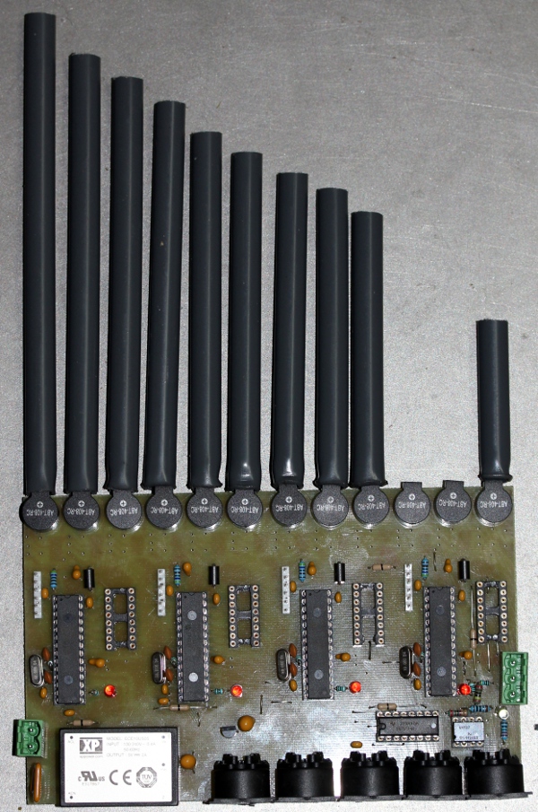 All four microcontrollers on this board programmed. We cannot test midi operation,
as we do not have the AND-gates in place for now.
All four microcontrollers on this board programmed. We cannot test midi operation,
as we do not have the AND-gates in place for now.
20.02.2017: The ordered AND-gates as well as the IRLZ34N came flowing in from
Farnell. We soldered then in and did a first test... indeed it seems to work.
GMT implementation added for testing. With all MOSFETS soldered in place, the
power supply oscillates and the processors do not start up. If we first start
up and when all pic's are working, connect the +5 V to the buzzer supply everything
works fine. So the undetermined state of the PIC outputs during start up causes
an overload on the power supply. One way or another we have to delay the power
for the buzzers until the PIC is up and running. Also we noticed pretty large
differences in the sound level for the different notes. It might have been better
to mount small 50 Ohm trimpots in series with the buzzers.
21.02.2017: PCB designs changed to accommodate small Omron 5 V relays to switch
the power to the buzzers after reception of a ctrl 66 command. As board 1 is
already made, we have to place the relay for this board on board 4. Boards 2
and 3 get a relay of their own. Impedance tables calculated for the sounders
and required series resistors to limit current calculated. Calculations based
on the datasheet lead to an inductance of 903uH for the sounders. Circuit drawings
updated accordingly. Vertical mounting plate cut out from 8 mm thick polycarbonate.
Steel mandrel made from steel for driving the square 6 x 6 holes into the 10
mm pipes. Some test pipes made from aluminum tube. This sounds a bit better
than PVC, probably due to the more shiny surface on the inside. The problem
with this material is in the way to connect it airtight to the mouths of the
buzzers. Epoxy glue?
22.02.2017: Further design work on the general assembly of the robot. Making
sure it will fit in an ordinary attaché case.
23.02.2017: Calculated resistors in series with the buzzers soldered in. New
pipe set made after careful tuning, from aluminum tube 10/8 for the lowest octave.
All pipe ends extruded to square holes using our special tool and an arbor press.
24.02.2017: Twelve alu pipes glued to the buzzers with fast setting epoxy glue.
Some bugs removed in the firmware: word overflows in the ADSR parameters...
A problem did rise up now however: the pipes, once glued do not resonate properly
anymore... Looks like we have to shorten them all. Thus it would be better to
first glue the buzzers to the pipes and tune them only with the buzzers in place.
Apparently, with loose tubes, the pipes resonate in a half wavelength mode with
very different end-corrections.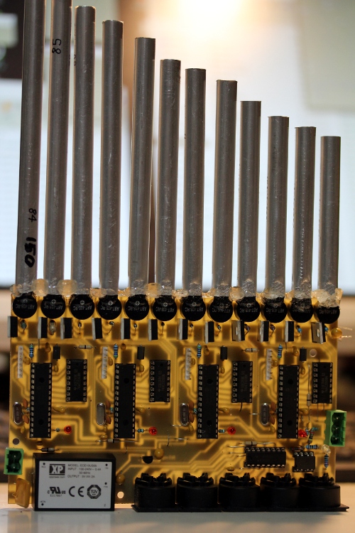
25.02.2017: Epoxy glue seems to be no good at all. It neither sticks well to
be buzzers nor to the pipes. All pipes removed again from board 1 and retuned/recalculated.
Now trying to glue the pipes to the buzzers using Loctite cyanoacrylate gel
glue. Although it is advertised as second-glue, the gel bubbles it makes, take
many hours to cure and dry fully. A preliminary pipe set made for board two:
notes 96 to 107. This is the board where we are expecting most tuning troubles
as this is the range of the membranes resonant frequency. PCB films made for
board 2,3 and 4. Etching done in the night... Drilling will be for tomorrow.
26.02.2017: Board for notes 120 to 127 drilled, assembled, tested and programmed.
For this board we need a different type of buzzer, as the sound level of the
ABT types is too low in this range. This board also holds the power-on relay
for board 1.
27.02.2017: Pipe construction for board 2. Decided to cut the pipes under an
angle. This greatly improves resonance and sound projection. However, we had
to construct all pipes over again... 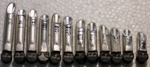 Board
2 drilled, soldered and programmed. The third microcontroler on this board failed
to program properly. It continuously reboots. Double checking the board did
not reveal any problem. Taking another chip solved the problem, so we had to
cope with a new but failing microprocessor...
Board
2 drilled, soldered and programmed. The third microcontroler on this board failed
to program properly. It continuously reboots. Double checking the board did
not reveal any problem. Taking another chip solved the problem, so we had to
cope with a new but failing microprocessor...
28.02.2017: Instabilities observed on the 3.3 V power on board 2. Replacing
the regulator with a TO220 package 2940.3V3 chip solved the problem. Pipes for
board 2 soldered in place. Drilling of board 3. Board 3 fully populated and
tested. The pipes for this board are still under construction. Start construction
of the chassis. 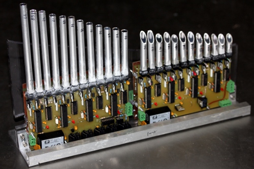 Although
a bit ridiculous in terms of functionality, we decided to give <Pi> four
wheels, just to match the design of the robot orchestra.
Although
a bit ridiculous in terms of functionality, we decided to give <Pi> four
wheels, just to match the design of the robot orchestra.
01.03.2017: Start wiring of the complete assembly with connectors. Figure-8
mains entry mount constructed. Mounting of the wheels with M5 bolts and nuts.
Finalizing the chassis. <Pi> implemented as member of the robot orchestra
in GMT. There still is a bug in the relay circuit. Controller 66 does not appear
to work. Pinning mistake? Thoroughly studying the datasheet
for the Omron relays revealed the mistake: the coils in these relays are
polarized! On boards 2 and 3 we poled them wrong. Board 4 is O.K.
02.03.2017: Bugs on relay poling on board 2 and 3 fixed. Now Ctrl.66 does work
indeed. Resonators constructed for notes 120 to 127. All notes are playing now.
Light mapped on midi note 0 tested as well. Left to be done: adjusting sound
levels for the individual pipes, intoning is what organs builders call this.
03.03.2017: ADSR coding debugged in the firmware. Here we have 9 bit resolution
on the amplitudes, as the PTPER-register is set to 512 in the code. Microtuning
implemented for all individual notes.
04.03.2017: Further development of microtuning implementation. Corrections on
the tuning seem required. Tuning code added to our GMT software. The resolution
on the highest notes is insufficient though. Also, in this very high register,
the imperfections of equal temperament become quite painfull... The fifths are
quite dissonant. For practical use, the sound levels with the transducers on
the highest board (notes 120-127) are too soft. We need to try another design
here. Start of experiments with conical resonators extruded from aluminum tube.
Series resistors on board 1 changed such as to obtain regular sound levels from
all pipes.
05.03.2017: The plastic tubes wherein DIL IC-sockets are packed make a good
material for the construction of TO220 package protectors and insulators. We
applied them to both sides of the <Pi> robot boards to protect the MOSFETS.
Further intoning work on board 2, notes 96 to 107. This is the board were we
have to deal with the own-resonance of the buzzers around the notes 100 and
101. After many hours of experimenting we must confess that's mission impossible,
for the required scalings appear to be volume and waveform dependent,.. A compromise
is unavoidable here. The tuning implementation must still have some bugs.
06.03.2017: We come to the conclusion that we need different drivers for the
notes on board 4. The KPX-G1205B drivers behave unreliably with changing volume.
Possible replacements, at least for notes 120-124, would be 15mm miniature loudspeakers.
For notes 125 to 127, our experiments led to the conclusion that only piezo
dome tweeters handle this reliably and with a reasonable volume. It must be
said however, that the waveform is quite irrelevant in this range as any overtones
fall out of the audioperception range anyway. This is what we first made, but
needed to reject:
| freq = f0 | driver | l/d | L | De | Di | Lambda/4 | R | |
| 120 | 8372 | KPX-G1205B | 1.25 | 2.0 / 18 | 10 | 8 | 10 | 0 |
| 121 | 8870 | KPX-G1205B | 1.18 | 2.0 / 17 | 10 | 8 | 9.7 | 0 |
| 122 | 9397 | KPX-G1205B | 1.18 | 3.0 / 16 | 10 | 8 | 9.2 | 0 |
| 123 | 9956 | KPX-G1205B | 1 | 3.0 / 13 | 10 | 8 | 8.6 | 0 |
| 124 | 10550 | ABT-407-RC | 1.2 | 6.0 | 10 | 5 | 8.2 | 0 |
| 125 | 11180 | ABT-407-RC | 1.1 | 5.5 | 10 | 5 | 7.7 | 0 |
| 126 | 11840 | ABT-407-RC | 0.7 | 6.0 | 12 | 8.5 | 7.3 | 0 |
| 127 | 12540 | ABT-407-RC | 0.77 | 3.5 | 10 | 4.5 | 6.9 | 0 |
The notes 120 to 125 are now driven by LSF-15M/S miniature loudspeakers, 8 Ohm impedance and 800mW power. Their diameter is 15 mm. We constructed a carrier board from epoxy plate material wherin the newly made 1/2 lambda resonator fit tightly. The speakers come with an adhesive layer on their circomference, but as we didn't trust the strenght, we fastened all components with a small driplet of cyanoacrylate glue. For the last two notes, 126 and 127, we ended up with Kemo piezoelectric tweeters. These are tuned with an inductance on the PCB. Their capacitance is 16.6nF., thus the calculated inductors would have to be 10.8mH and 0.97mH. We can take 10mH for both of them. So the new sizing becomes:
| freq = f0 | driver | l/d | L | De | Di | Lambda/2 | L | |
| 120 | 8372 | LSF-15M/S | 2.29 | 20.6 / 16.1 | 10 | 8 | 10 | |
| 121 | 8870 | LSF-15M/S | 2.14 | 19.4 / 14.9 | 10 | 8 | 9.7 | |
| 122 | 9397 | LSF-15M/S | 2.02 | 18.4 / 13.9 | 10 | 8 | 9.2 | |
| 123 | 9956 | LSF-15M/S | 1.88 | 17.3 / 12.8 | 10 | 8 | 8.6 | |
| 124 | 10550 | LSF-15M/S | 1.76 | 16.3 / 11.8 | 10 | 8 | 8.2 | |
| 125 | 11180 | LSF-15M/S | 1.64 | 15.4 / 10.8 | 10 | 8 | 7.7 | |
| 126 | 11840 | Kemo Dome | 0.36 | [14.6] 7.5 | 30 | 21 | 7.3 | 10mH par |
| 127 | 12540 | Kemo Dome | 0.36 | [13.8] 7.5 | 30 | 21 | 6.9 | 8.2mH |
We tried to give the two highes notes resonantors as well, but none of our
experiments lead to a convincing result. The diameter of the Kemo drivers is
just way to large to obtain resonance with a cylindric resonator. Here is a
picture of board 4: 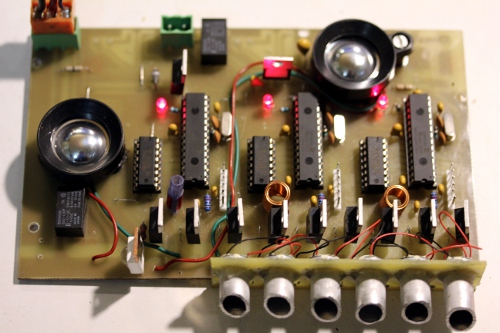
07.03.2017: Remark with regard to capacitance measurement of piezo-electric
materials: When measuring capacitance with a Hameg LCR meter, no reliable results
can be obtained from the display as it constantly shows widely different values.
The same for the Fluke 87 IV multimeter. In long time averaging mode only, the
value of 16.6nF was obtained. The explanation for this requires a better understanding
of piezo-electric disks. Although they mostly behave as a capacitor (they do
not pass DC) , their equivalent circuit is quite complex:  (cfr. 'Piezoelectric Ceramics, properties and applications', Philips Components,1991)
So a better approach to practical measurement is by measuring the impedance
at a given frequency. However, even then, the value will be a function of the
excitation level as well. After some experimentation, we decided to use 8.2mH
and 10mH coils. All PIC's on boards 3 and 4 reprogrammed, with gradual scalings
for the wave form duty cycles. Construction of U-shaped pipe protection profiles
to be mounted on both sides. After this mount, we consider <Pi> visually
to be finished. Picture time. Further improvements will either be on the board
electronics or on the firmware. Here is another view:
(cfr. 'Piezoelectric Ceramics, properties and applications', Philips Components,1991)
So a better approach to practical measurement is by measuring the impedance
at a given frequency. However, even then, the value will be a function of the
excitation level as well. After some experimentation, we decided to use 8.2mH
and 10mH coils. All PIC's on boards 3 and 4 reprogrammed, with gradual scalings
for the wave form duty cycles. Construction of U-shaped pipe protection profiles
to be mounted on both sides. After this mount, we consider <Pi> visually
to be finished. Picture time. Further improvements will either be on the board
electronics or on the firmware. Here is another view: and the back side with the highest pitched pipes:
08.03.2017: Some artefacts observed on notes in the highest octave. These must
be attributed to interference with the switching frequency of the power supply
modules, as the problem did not occur with our external lab supply. Starting
to implement just intonation tunings in the firmware. We succeeded in implementing
the 16-bit timers with prescalers set to 0. This is an 8-fold improvement in
pitch precision. With this coding however the lowest note we could possibly
generate would be midi 82. Not a problem for <Pi>, but it will be a problem
if we use the firmware for a commercial serinette project.
09.03.2017: Microtuning for every single note implemented, as well as just intonation
tuning tables calculated for each of the twelve possible fundamentals. Frequency
errors are now <= 0.05%. Comments on the coding can be found in the headers
of the source code for the firmware. After these firmware changes, we noticed
glitches every so often. We still have to sort this out.
10.03.2017: Version 1.6 of the firmware flashed. This version has better than
0.02% precision in frequencies and improved lookup tables for just intonation
tunings. The lookup tables are generated by a small utility program written
in PBCC based on precise real-world measurements on the test board. The formula
to be used for period calculations should be period = ((1/freq) - t)/ k. In
this formula t is the time lost in the timer ISR, measured to be 1.3 us, and
k = 1 / 60MHz, or 16.6 ns.
11.03.2017: Torture code written to test limits on polyphony. Indeed, as was
to be expected, we cannot play 44 note clusters at maximum volumes as the power
supplies go into current protection mode.
12.03.2017: There seems to be a PIC-crash condition on boards 2 and 3, when
many notes are playing at high volumes. We suspect the high frequency switching
of the inductive buzzers without protection diodes and without series resistors
cause serious glitches on the power supply lines. Better supply bypassing is
required. Another issue might be that when a single PIC sounds three notes,
the interrupt density is so high that there is no place anymore to serve the
midi interrupt properly.
13.03.2017: Demo piece for <Pi> composed and tested. This is an algorithmic
composition integrated in and playable from the <Pi> section in our GMT
software.
14.03.2017: The finishing touch on 'Pipi' on Pi-day.  Finishing the construction of a flightcase for Pi. It's a modified aluminum
attache case. Recording session of the piece. Curious to find out whether that
will work as an MP3. Here is the MP3. We also
posted the link on Facebook.
Finishing the construction of a flightcase for Pi. It's a modified aluminum
attache case. Recording session of the piece. Curious to find out whether that
will work as an MP3. Here is the MP3. We also
posted the link on Facebook.
16.09.2018: <Pi> packed in its flightcase as it leaves for two months
to Manchester, together with <Krum>, <Bomi>, <Bourdonola>.
<Pi>'s role in the orchestra can in part be taken over by the newborn
<2Pi> robot.
23.10.2018: <Pi> returned from Manchester, seriously damaged... Check-up
and repair required.
25.10.2018: Connector (Weidmueller 3 pole) replaced on board 4. Pipe for note
84 repaired and fixed again.
25.02.2020: <Pi> demonstration for Luc Ponnet.
24.03.2020: A major accident happened to <Pi>. It fell down from in top
of the piano on our steel floor in the Logos tetrahedron. 18 pipes broke off
and the transducers are severely damaged. Right now <Pi> is in the intensive
care section of the Logos Hospital. Let's hope it will recover soon...
25.03.2020: Reconstruction of the 12 lowest pipes. Suffering a bit under the
quite noxious vapors from the cyanoacrylates we use to hold the pipes in place.
By midnight the PCB was reassembled again. The second octave is for tomorrow...
26.03.2020: Repair of the second octave. By the end of the day, <Pi> was
fully operational again. We should make a standing base for <Pi> such
that this kind af accident can never happen again.
07.12.2020: Timer 23 bug found and killed in the PIC 24EP code for all the PIC's
here. We must read TMR3HLD instead of TMR3 when combining timer 2 and 3 as a
32 bit timer. This explains the unpredictable amplitude glitches we had every
so often.
TO DO:
- optimizing the firmware
- extensive testing
- apply 'intellitune' in the firmware to avoid the fifth dissonances due to
equal temperament.
- suggested changes for further future designs:
Maintenance information:
Circuit diagrams:
Board 1: (notes 84-95)
Boards 2 and 3:
Board 4:
PCB for board 1: notes 84 to 95 (scaled 200%)
PCB for boards 2 and 3: notes 96 to 107 and 108 - 119 respectively (scaled 200%)
This is the board -with errors- as used with manual corrections in the <Pi> robot:
A corrected PCB design is available as well and will be used for future and further production.
PCB for board 4: notes 120 to 127 (scaled 200%)
Microcontroller firmware:
source code (to be separately compiled for each of the 15 microprocessors).
If people are interested in owning a copy of this miniature robot, I can hand make them for ca. 5000 Euro. Delivery time will be ca. 2 months. Smaller and cheaper versions would be possible as well, for instance 30 notes starting from midi note 79. Feel free to enquire. Estimated cost for a 30 note version would be 3000 Euro maximum.
Cost calculation for the Pi robot:
Main board (12 notes):
| item / part | NR. | description | price |
| 24EP128M0202 | 4 | Microchip |
15.00
|
| IC socket | 4 | 28 pins |
8.00
|
| IC socket | 5 | 16 pins |
6.50
|
| 6N137 | 1 | optocoupler |
2.00
|
| PCB | 1 | 100 x 160 + processing |
50.00
|
| Sounders | 12 | ABT408RC |
14.00
|
| IC socket | 1 | 8 pins |
1.00
|
| SMPS 5V - 2A | 1 | XP Power ECB10US05 |
30.00
|
| 5-pole DIN sockets | 5 | Hirshmann |
20.00
|
| 74AC11008N | 4 | 3V/5V AND-gates |
6.00
|
| SN75174 | 1 | quad differential line driver |
4.00
|
| 1 | 3V3 voltage regulator |
2.50
|
|
| ICD headers 6-pins | 4 |
2.00
|
|
| IRLZ34NPbF | 12 | power MOSFET |
18.00
|
| 2 pole Weidmueller | 2 | socket and plug |
8.00
|
| 3 pole Weidmueller | 1 | socket and plug |
3.50
|
| Fuse | 1 | self resetting fuse |
1.00
|
| Tantalum capacitors | 10 |
20.00
|
|
| 100nF bypass caps | 18 |
4.50
|
|
| Resistors | 21 |
2.10
|
|
| LED's | 5 |
2.50
|
|
|
220.60
|
Boards 2 and 3:
| item / part | NR. | description | price |
| 24EP128M0202 | 4 | Microchip |
15.00
|
| IC socket | 4 | 28 pins |
8.00
|
| IC socket | 4 | 16 pins |
6.00
|
| PCB | 1 | 100 x 160 + processing |
50.00
|
| Sounders | 12 | ABT408RC |
14.00
|
| SMPS 5V - 2A | 1 | XP Power ECB10US05 |
30.00
|
| 74AC11008N | 4 | 3V/5V AND-gates |
6.00
|
| 1 | 3V3 voltage regulator |
2.50
|
|
| ICD headers 6-pins | 4 |
2.00
|
|
| IRLZ34NPbF | 12 | power MOSFET |
18.00
|
| 2 pole Weidmueller | 2 | socket and plug |
8.00
|
| 3 pole Weidmueller | 1 | socket and plug |
3.50
|
| Fuse | 1 | self resetting fuse |
1.00
|
| Tantalum capacitors | 10 |
20.00
|
|
| 100nF bypass caps | 18 |
4.50
|
|
| Resistors | 21 |
2.10
|
|
| LED's | 5 |
2.50
|
|
| Omron Relay | 1 | G6E-134P-ST-US |
5.00
|
|
190.10
|
Board 4:
| item / part | NR. | description | price |
| 24EP128M0202 | 3 | Microchip |
10.00
|
| IC socket | 3 | 28 pins |
6.00
|
| IC socket | 3 | 16 pins |
4.50
|
| PCB | 1 | 100 x 160 + processing |
50.00
|
| Sounders | 8 |
10.50
|
|
| 74AC11008N | 3 | 3V/5V AND-gates |
4.50
|
| 1 | 3V3 voltage regulator |
2.50
|
|
| ICD headers 6-pins | 3 |
1.50
|
|
| IRLZ34NPbF | 9 | power MOSFET |
15.00
|
| 2 pole Weidmueller | 2 |
8.00
|
|
| 3 pole Weidmueller | 1 |
3.50
|
|
| Tantalum capacitors | 10 |
20.00
|
|
| 100nF bypass caps | 12 |
3.00
|
|
| Resistors | 40 |
4.00
|
|
| LED's | 3 |
1.50
|
|
| 1W Power LED | 1 | Yellow, TO220 |
4.00
|
| Omron Relay | 2 | G6E-134P-ST-US |
10.00
|
| Kemo dome tweeters | 130269 | ||
|
158.50
|
Mechanical parts and general assembly::
| item / part | NR. | description | price |
| polycarbonate plate material | 1 | 400 x 300 x 8 |
4.00
|
| aluminium brackets | 4 | 30 x 50 x 3 |
2.00
|
| aluminum profile | 50 x 2 x 10 |
3.00
|
|
| M3 bolts and nuts | 24 | stainless steel |
12.00
|
| M4 bolts and nuts | 4 | inbus hex stainless |
3.00
|
| M5 bolts and nuts | 12 |
6.00
|
|
| M5 end nuts, stainless | 8 | DIN1587 RVS-A1 M5 |
5.00
|
| aluminum profile square | 1 | 80 x 2 x 15 |
5.00
|
| wheels | 4 |
22.00
|
|
| Aluminum pipe 10/8 mm | 2 meters |
10.00
|
|
| PVC pipe 10/8 mm | 2 meters |
6.00
|
|
| Epoxy glue | 1 | fast setting |
10.00
|
| 5 mm distance holders | 16 | 3 mm |
4.00
|
| Loctite Cyanoacrylate glue | 4 | gel |
38.00
|
| Power cord | 1 | figure-8 plug |
2.00
|
| MIDI cable, angled connector | 1 |
12.00
|
|
| Flightcase (attache case) | 1 |
30.00
|
|
|
174.00
|
total cost for materials: 935.30 Euro
Labor and research investment:
15.02.2017 ---> 09.03.2017: 24 working days. 7.560 Euro.
End cost of prototype production: 8.500 Euro
Repair costs march 2020:
18 sounders replaced: 24 Euro
Cyanoacrylate: 12 Euro
3 working days: 945 Euro
End sum: 981 Euro.
by Godfried-Willem Raes
Further reading on this topic (some in Dutch):
Audsley, George Ashdown 'The Art of Organ-Building', ed. Dover Inc, NY,1965,
(first edition: 1905) ISBN 0-486-21314-5
D'Appolito, J. 'Luidspreker-meettechniek', ed. Segment BV, Beek , Nederland,
2000, ISBN: 90 5381 116 8
De Keyser, Ignace, 'Challenging
von Hornbostel & Sachs', in: 50 years at Logos, 2019
Philips Components, 'Piezoelectric Ceramics, properties and applications', Eindhoven,1991
Raes, Godfried-Willem 'Bug', an automated fluegelhorn (2017)
Raes, Godfried-Willem , Expression
control in musical automatons
Maintenance and disassembly instructions:
For removing the PCB's as well as for servicing the Weidmueller connectors, the 15 x 15 mm aluminum profile should be removed first.
Robody picture with <Pi>:
Candidates?
[EOF]